1 2
ON
PLAY
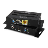
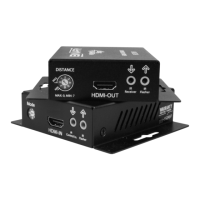
FIGURE 3 : Application Diagram
Note: When a power supply is connected to either the transmitter or receiver, the HDBaseT
link sends power to the other unit. Only one unit requires a power supply to be connected.
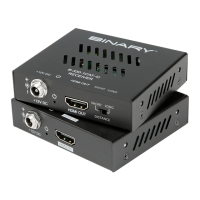
6.1. HDBaseT Link (RJ45) Connection
This device is specied to operate with category cables for communication between the
transmitter and receiver. The transmission path may include a maximum of two keystones and
two patch cables, as long as the total length does not exceed 200' for Cat 5e/6 and 230' for Cat
6a/7.
FIGURE 4: RJ45 Connections
Note: The HDBaseT Link RJ45 connection includes a 12V signal. Do not connect anything to
this port other than an HDBaseT transmitter or receiver.
HDMI Source
AC
Power
Back Front
B-540-EXT-230-RS Receiver
B-540-EXT-230-RS Transmitter