1 2
ON
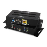
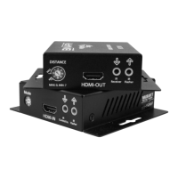
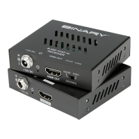
FIGURE 2: Receiver Layout
A. Thread-locking Power Connector
Connect to the included 24VDC,1A power Supply
B. Power LED
Lights up blue when the unit has power
C. HDMI Out
HDMI Output to connect to the HDMI input of a sink(display)
D. IR Flasher
IR output to connect to IR Flasher
E. IR Receiver
IR input to connect to IR Receiver or to output of a control system
F. DIP Switches
DCE/DTE
Select for DTE or DCE mode serial (RS232) communication via DB-9
ON/SERVICE
ONfor Pass-Through (normal operation)/Service for Firmware update
G. RS-232
Connect to communicate RS-232 commands when connected to a control system
H. HDBaseT (RJ45 )
Connect to the HDBaseT RJ45 port on receiver
I. Link LED
Lights green when synced with receiver
A B C D E F
G
H I