9
6.2. IR Control Connections
Bidirectional IR signals can be transmitted between transmitter and receiver through category
cable. The IR signal can be generated either from a powered receiver or from a control system.
The following section describes these two use cases.
CAUTION: Pinout configurations for IR receivers and control systems vary. Before
connecting to this input, review this section carefully in order to match the pinouts for the
device.
IR OutputsIR Inputs
PLAY
+24VDC1A
INPUT
PWR
HDMI OUT
+24VDC1A
INPUT
PWR
Control In
HDMI IN
RS-232 LINK
DTE
DCE
ON
SERVICE
5 3 2
HDBaseT
1 2
ON
1 2
ON
D
B
C
A
C
or
FIGURE 5: IR Connections
Note: Arrow direction indicates signal ow.
IR Control In-3.5 mm Mono—See Section 6.2.2
IR Receiver In-3.5 mm Stereo—See Section 6.2.1
IR Flasher Out-3.5 mm Mono—See Section 6.2.3
D HDBaseT Link category cable (RJ45)—See Section 6.1
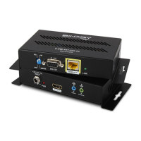
B-540-EXT-230-RS Receiver
B-540-EXT-230-RS Transmitter
IR Processor/ Controller
HDMI Source
HDBaseT
Back Front