Page 9 of 1281883X
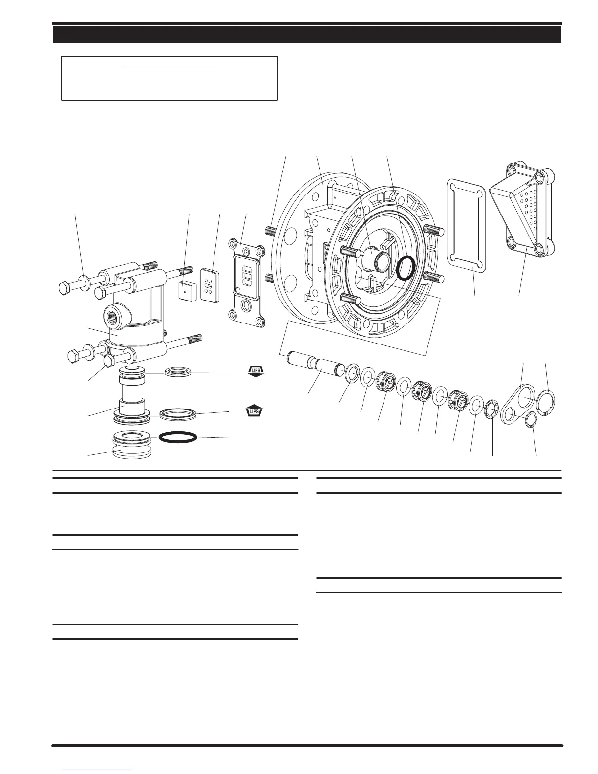
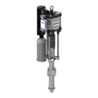
PARTS LIST / 81883X AIR MOTOR SECTION
PILOT VALVE
MAJOR VALVE
Figure 5
. TORQUE REQUIREMENTS ,
NOTE: DO NOT OVERTIGHTEN FASTENERS.
(134) Torque to 15 Ć 20 in. lbs (1.7 Ć 2.3 Nm), wait 10 minutes, then
reĆtorque to 15 Ć 20 in. lbs (1.7 Ć 2.3 Nm).
136
129130
102103101131
132141140
111
135
137
139
138
118
142
142 122
104143
119
119
119
119
120
120
120
133
. 134
AIR MOTOR SECTION SERVICE
Service is divided into two parts Ć 1. Pilot Valve, 2. Major Valve.
S Air Motor Section Service is continued from Fluid Section repair.
PILOT VALVE DISASSEMBLY
1. Remove (122 and 104) snap rings.
2. Remove (143) plates.
3. Remove (103) sleeve and (102) O" rings.
4. Remove (118) pilot rod, (142) washers, (119) O" rings and (120)
spacers from (101) center body.
PILOT VALVE REASSEMBLY
1. Assemble (119) O" rings, (120) spacers and (142) washers on (118)
pilot rod.
2. Insert the stack into the (101) body. Sleeve (103) may be used to asĆ
sist pressing stack into body.
3. Install (103) sleeve and (102) O" rings into (101) body.
4. Install (143) plates and (122 and 104) snap rings.
MAJOR VALVE DISASSEMBLY
1. Remove (129) muffler and (130) gasket.
2. Pull (135) valve block assembly from (101) motor body.
3. Remove (134) bolts, (133) washers and (132) gasket from (135)
valve block.
4. Remove (141) valve plate and (140) valve insert.
5. Remove (136) plug and (111) spool.
MAJOR VALVE REASSEMBLY
1. Install new (139 and 138) U" cups on (111) spool Ć LIPS MUST
FACE EACH OTHER.
2. Insert (111) spool into (135) valve block.
3. Install (137) O" ring on (136) plug, insert plug into (135) valve block.
4. Install (140) valve insert and (141) valve plate into (135) valve block.
Note: Assemble (140) valve insert with dished" side toward (141)
valve plate. Assemble (141) valve plate with 2 identification dots toĆ
ward (132) gasket.
5. Replace (132) gasket and install valve block assembly on (101)
body.