ECO Cooling Soluons INSTALLATION GUIDE
ENG
28
>
29
>
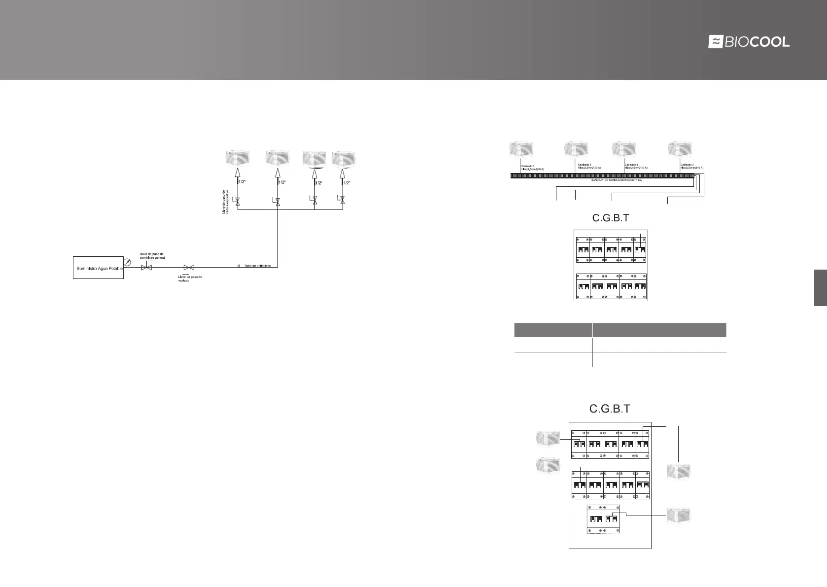
Water scheme example
Considerations to take into account in the installation of plumbing:
• Place a shut-off valve to all machines.
• Place a draining shut-off valve to prevent accumulation of water in winter and
freezing problems.
• Make use of a shut-off valve for each installed unit and be able to cut the supply
in specific equipment.
• Use polyethylene pipe diameter corresponding to water supply connections.
• Entry to the evaporative will be /” and the electrovalve located before the
evaporative will be a /” female input and output.
• Check if the supply pressure is the necessary for supplying the full installation.
• Checking the plumbing connection of the entire installation to avoid losses and
leaks that can cause damage.
CONNECTION DIAGRAMS
MODELO
WIRING TYPE
BIO-D
wires of , mm2 section ( A)
BIO-D
Three-phase cable(N+3F+Ground)
Connection diagram example



 To Next Page