15 Biodex Medical Systems, Inc. © 2018
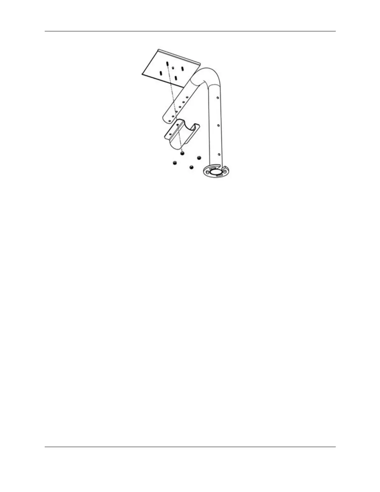
Figure 2.9. Attaching/Removing the Interface Module to the Interface Module Shelf.
3. Place the Tablet Shelf on the arm assembly with the shelf tube clamp positioned on the
other side of the support tube lining up the screw holes with the screw holes in the Atomlab
Tablet Shelf. Put the nuts onto the posts and tighten them (see Figure 2.9).
Atomlab 500Plus and Wipe Test Counters
Note: Refer to the Atomlab™ 500, Atomlab™ 500plus Dose Calibrator, and Atomlab™ Wipe Test
Counter Installation Guide for instructions on cable connections and Power Up instructions.
1. Position the Wipe Test Counter on the cabinet in front of the Display/Tablet Shelf, on a
shelf, or on a nearby table.
Note: If placing the Wipe Test Counter off the cabinet top, keep in mind the RJ-12 cable is
only 8’ in length and one end must be connected to the Atomlab 500 Detector.
Complete the Atomlab Installation
WIN CE Display:
1. Connect the chamber signal cable to the back of the Dose Calibrator.
2. Plug the power cord into the back of the Dose Calibrator.
3. Run the power cable down the support tube and over the back wall of the cabinet.
4. Fasten both the chamber signal cable and the power cord at the base and along the support
tube with the supplied tie wraps.
5. Plug the Dose Calibrator power cord into a wall socket. The PET Unit Dose Cabinet is ready
for use.