945GC-M7 TE
7
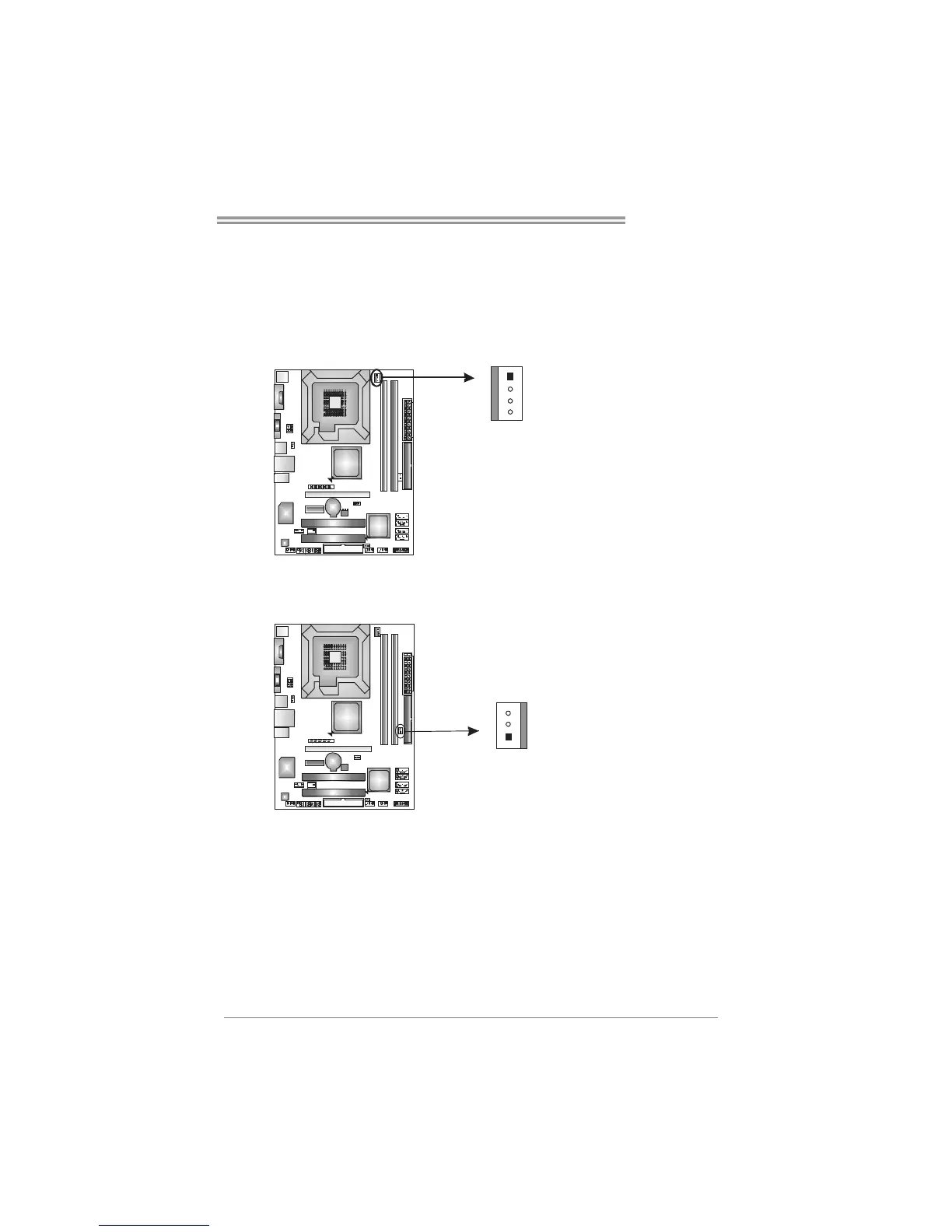
2.2 FAN HEADERS
These fan headers support cooling-fans built in the computer. The fan
cable and connector may be different according to the fan manufacturer.
Connect the fan cable to the connector while matching the black wire to
pin#1.
JCFAN1: CPU Fan Header
Pin
Assignment
1 Ground
2 +12V
3 FAN RPM rate
sense
1
4
4 Smart Fan
Control
JSFAN1: System Fan Header
Pin
Assignment
1 Ground
2 +12V
1
3
3 FAN RPM rate
sense
Note:
The JCFAN1 and JSFAN1 support 4-pin and 3-pin head connector. When connecting
with wires onto connectors, please note that the red wire is the positive and should be
connected to pin#2, and the black wire is Ground and should be connected to GND.
 Loading...