Motherboard Manual
14
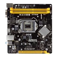
F_AUDIO1: Front Panel Audio Header
This header allows users to connect the front audio output cable with the PC
front panel.
HD Audio AC’97
Pin Assignment Pin Assignment
1 Mic Left in 1 Mic In
2 Ground 2 Ground
3 Mic Right in 3 Mic Power
4 GPIO 4 Audio Power
5 Right line in 5 RT Line Out
6 Jack Sense 6 RT Line Out
7 Front Sense 7 Reserved
8 Key 8 Key
9 Left line in 9 LFT Line Out
10 Jack Sense 10 LFT Line Out
Note1: It is recommended that you connect a high-definition front panel audio module to
this connector to avail of the motherboard's high definition audio capability.
Note2: Please try to disable the "Front Panel Jack Detection" if you want to use an AC'97
front audio output cable. The function can be found via O.S. Audio Utility.
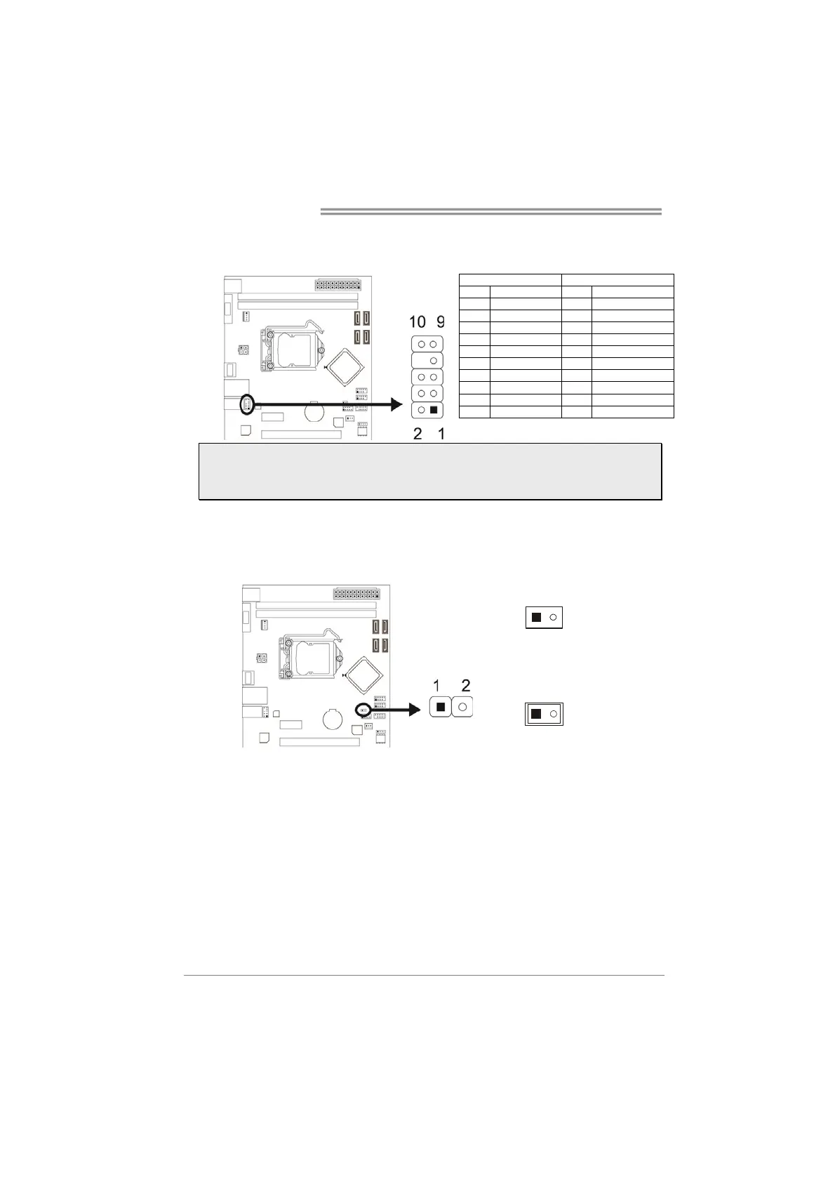
JCMOS1: Clear CMOS Jumper
The jumper allows users to restore the BIOS safe setting and the CMOS data.
Please carefully follow the procedures to avoid damaging the motherboard.
1
2
Pin 1-2 Open:
Normal Operation (default).
1
Pin 1-2 Close:
Clear CMOS data.
※ Clear CMOS Procedures:
1. Remove AC power line.
2. Set the jumper to “Pin 1-2 close”, you can use a metal object like a
screwdriver to touch the two pins.
3. Wait for five seconds.
4. After clearing the CMOS values, be sure the jumper is “Pin 1-2 open”.
5. Power on the AC.
6. Load Optimal Defaults and save settings in CMOS.
 Loading...