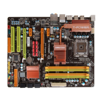
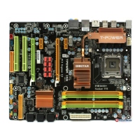
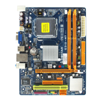
I945P-A7
21
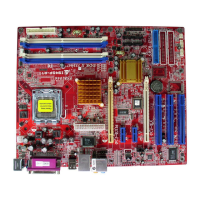
SATA1~SATA4: Serial ATA Connectors
The motherboard has a PCI to SATA Controller with 4 channels SATA interface,
it satisfies the SATA 2.0 spec and with transfer rate of 3Gb/s.
Pin
Assignment
1 Ground
2 TX+
3 TX-
4 Ground
5 RX-
6 RX+
SATA4
SATA1SATA2
SATA3
1
7
4
Code c
C
O
M
1
7 Ground
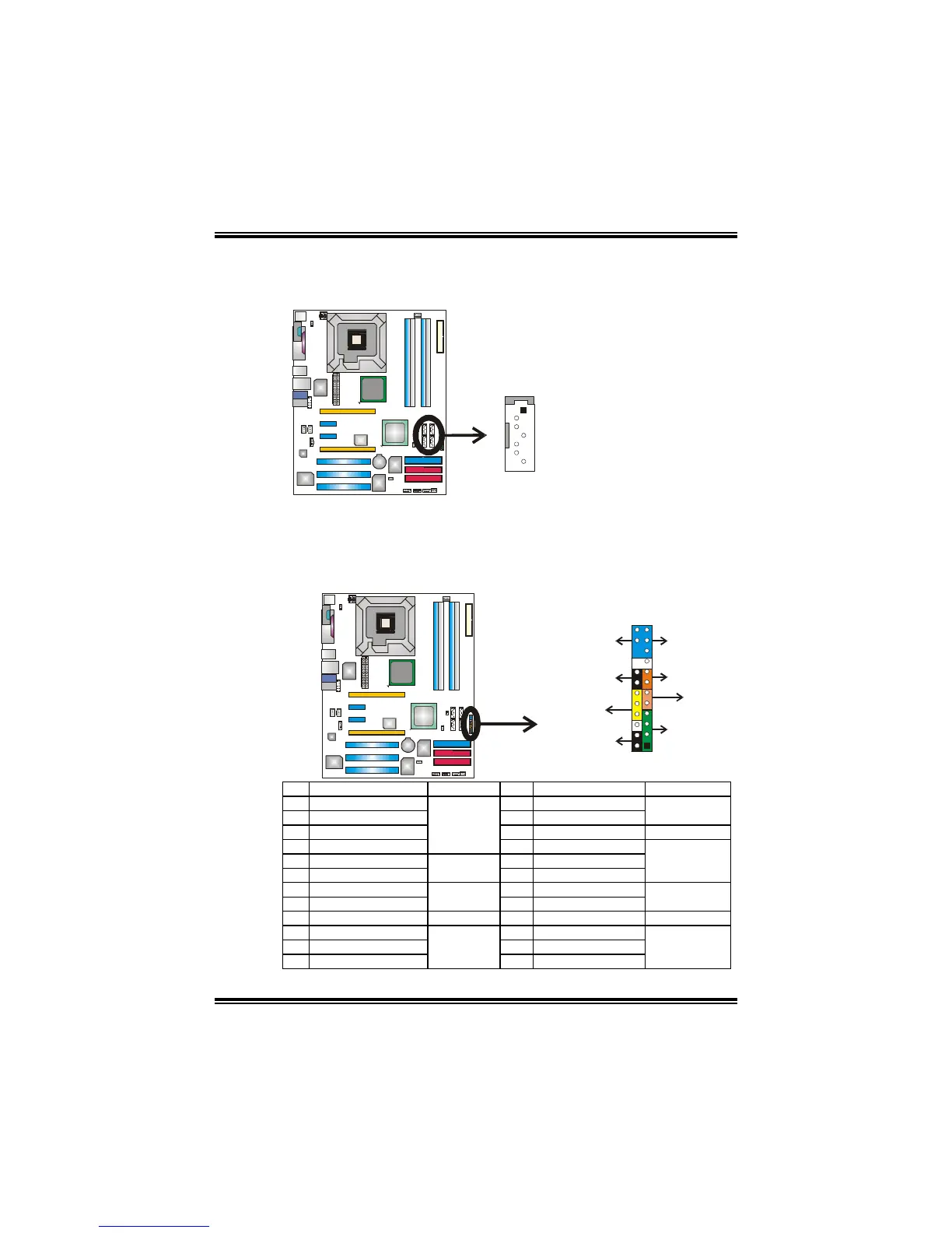
JPANEL1: Front Panel Header
This 24-pin connector includes Power-on, Reset, HDD LED, Power LED, Sleep
button, speaker and IrDA Connection. It allows user to connect the PC case’s
front panel switch functions.
1
2324
SLP
PWR_LED
On/Off
IR IR
RST
HLED
SPK
++
+
2
-
-
Code c
C
O
M
1
Pin Assignment Function Pin Assignment Function
1 +5V 2 Sleep control
3 N/A 4 Ground
Sleep button
5 N/A 6 N/A N/A
7 Speaker
Speaker
Connector
8 Power LED (+)
9 HDD LED (+) 10 Power LED (+)
11 HDD LED (-)
Hard drive
LED
12 Power LED (-)
Power LED
13 Ground 14 Power button
15 Reset control
Reset button
16 Ground
Power-on button
17 N/A 18 Key
19 N/A 20 Key
21 +5V 22 Ground
23 IRTX
IrDA
Connector
24 IRRX
IrDA Connector
 Loading...