EasyManuals Logo

Biostar MCP6P M2 PLUS User Manual

Biostar MCP6P M2 PLUS
47 pages
To Next Page IconTo Next Page
To Previous Page IconTo Previous Page
Page #15 background imageLoading...
Page #15 background image
MCP6P M2+/N68S+
13
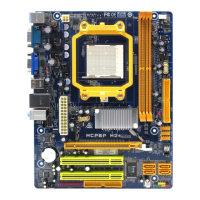
JATXPWR1: ATX Power Source Connector
This connector allows user to connect 24-pin power connector on the ATX
power supply.
1
12
13
24
Pin Assignment Pin Assignment
13 +3.3V 1 +3.3V
14 -12V 2 +3.3V
15 Ground 3 Ground
16 PS_ON 4 +5V
17 Ground 5 Ground
18 Ground 6 +5V
19 Ground 7 Ground
20 NC 8 PW_OK
21 +5V 9 Standby Voltage+5V
22 +5V 10 +12V
23 +5V 11 +12V
24 Ground 12 +3.3V
JATXPWR4: ATX Power Source Connector
By connecting this connector, it will provide +12V to CPU power circuit.
Pin
Assignment
1 +12V
2 +12V
3 Ground
1
32
4
4 Ground
Note:
Before power on the system, please make sure that both JATXPWR1 and JATXPWR4
connectors have been plugged-in.
Questions and Answers:

Question and Answer IconNeed help?

Do you have a question about the Biostar MCP6P M2 PLUS and is the answer not in the manual?

Biostar MCP6P M2 PLUS Specifications

General IconGeneral
Form FactorMicro ATX
Memory Slots2 x DIMM
AudioRealtek ALC662 6-Channel HD Audio
Storage Interface4 x SATA 3Gb/s
Integrated GraphicsNVIDIA GeForce 6150SE
USB Ports8 x USB 2.0 (4 rear, 4 via headers)
ChipsetNVIDIA GeForce 6150SE / nForce 430
Expansion Slots1 x PCIe x16, 1 x PCIe x1, 1 x PCI

Related product manuals