EasyManuals Logo

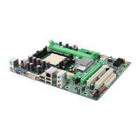
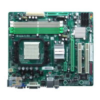
Biostar MCP6P M2 PLUS User Manual

Biostar MCP6P M2 PLUS
47 pages
To Next Page IconTo Next Page
To Previous Page IconTo Previous Page
Page #18 background imageLoading...
Page #18 background image
Motherboard Manual
16
JSPDIF_OUT1: Digital Audio-out Connector
This connector allows user to connect the PCI bracket SPDIF output header.
Pin
Assignment
1 +5V
2 SPDIF_OUT
13
3 Ground
JCMOS1: Clear CMOS Header
By placing the jumper on pin2-3, it allows user to restore the BIOS safe setting
and the CMOS data, please carefully follow the procedures to avoid damaging
the motherboard.
13
Pin 1-2 Close:
Normal Operation
(default).
13
13
Pin 2-3 Close:
Clear CMOS data.
Clear CMOS Procedures:
1. Remove AC power line.
2. Set the jumper to “Pin 2-3 close”.
3. Wait for five seconds.
4. Set the jumper to “Pin 1-2 close”.
5. Power on the AC.
6. Reset your desired password or clear the CMOS data.
Questions and Answers:

Question and Answer IconNeed help?

Do you have a question about the Biostar MCP6P M2 PLUS and is the answer not in the manual?

Biostar MCP6P M2 PLUS Specifications

General IconGeneral
Form FactorMicro ATX
Memory Slots2 x DIMM
AudioRealtek ALC662 6-Channel HD Audio
Storage Interface4 x SATA 3Gb/s
Integrated GraphicsNVIDIA GeForce 6150SE
USB Ports8 x USB 2.0 (4 rear, 4 via headers)
ChipsetNVIDIA GeForce 6150SE / nForce 430
Expansion Slots1 x PCIe x16, 1 x PCIe x1, 1 x PCI

Related product manuals