EasyManuals Logo

Biostar MCP6P-M2 User Manual

Biostar MCP6P-M2
45 pages
To Next Page IconTo Next Page
To Previous Page IconTo Previous Page
Page #15 background imageLoading...
Page #15 background image
MCP6P-M2
15
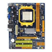
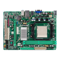
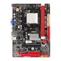
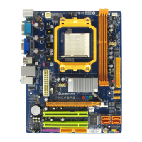
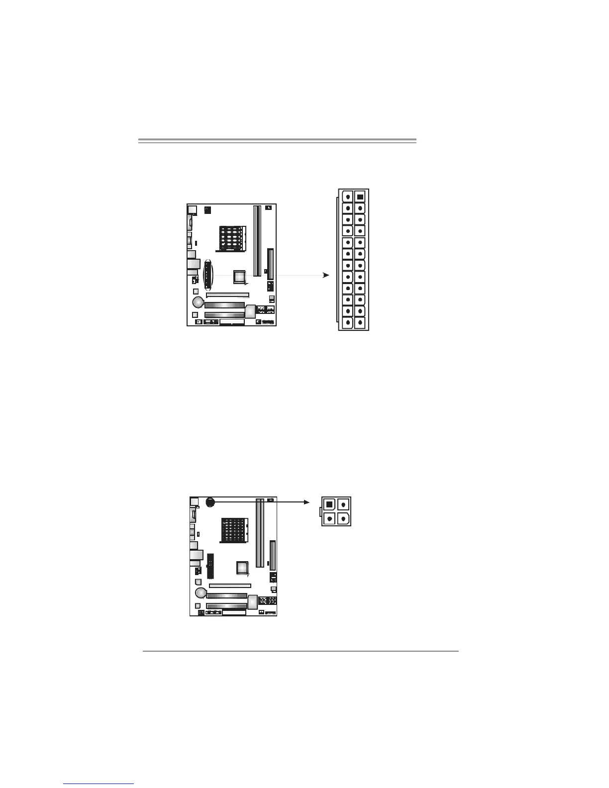
J ATXP W R1 : ATX Po we r S ou rce C onne ct o r
This connector allows user to connect 24-pin power connector on the ATX
power supply.
1
12
13
24
Pin Assignment Pin Assignment
13 +3.3V 1 +3.3V
14 -12V 2 +3.3V
15 Ground 3 Ground
16 PS_ON 4 +5V
17 Ground 5 Ground
18 Ground 6 +5V
19 Ground 7 Ground
20 NC 8 PW_OK
21 +5V 9 Standby Voltage+5V
22 +5V 10 +12V
23 +5V 11 +12V
24 Ground 12 +3.3V
J ATXP W R4 : ATX Po we r S ou rce C onne ct o r
By connecting this connector, it will provide +12V to CPU power circuit.
Pin
Assignment
1 +12V
2 +12V
3 Ground
1
3
2
4
4 Ground

Other manuals for Biostar MCP6P-M2

Questions and Answers:

Question and Answer IconNeed help?

Do you have a question about the Biostar MCP6P-M2 and is the answer not in the manual?

Biostar MCP6P-M2 Specifications

General IconGeneral
Form FactorMicro ATX
CPU SocketAM2
Memory TypeDDR2
Maximum Memory4GB
Storage InterfaceSATA, IDE
SATA4 x SATA 3Gb/s
IDE1 x IDE
Audio ChipsetRealtek ALC662
Audio Channels6-Channel
LAN ChipsetRealtek RTL8201CL
Max. LAN Speed10/100Mbps
PS/21 x PS/2 Keyboard, 1 x PS/2 Mouse
CPU TypeAMD Athlon 64 X2 / Athlon 64 / Sempron
Memory Slots2
Expansion Slots1 x PCI-E x16 1 x PCI-E x1 2 x PCI
USB Ports4 x USB 2.0

Related product manuals