Bird Model 5000 Digital Power Meter
12
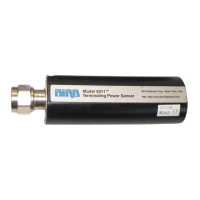
Terminating Power Sensor (TPS)
RF connections are the same for the TPS-EF and the
TPS. In most cases, the TPS should be connected to an
attenuator or a directional coupler. For example, to
measure a transmitter with power output between 0.1
and 50 Watts, use a 40 dB, 50 Watt attenuator. Insert
the attenuator between the TPS and the RF source.
Only connect the TPS directly to the source if the RF
power will be less than 10 mW.
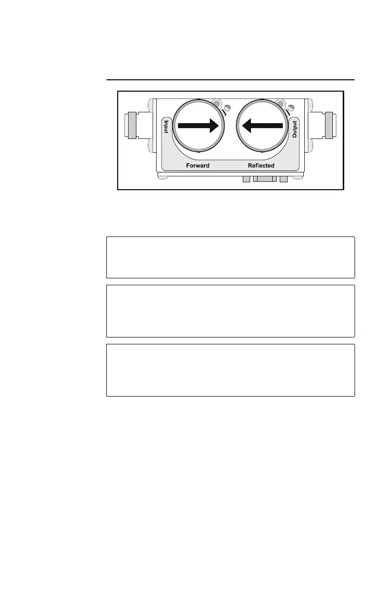
Figure 5 DPS Element Orientation
CAUTION
Ground all instruments before connecting the
TPS(-EF). Electric shock could damage the sensor.
CAUTION
When connecting the TPS or the TPS-EF, only turn
the connector nut. Damage may occur if torque is
applied to the sensor body.
CAUTION
Do not exceed 2 W average or 125 W peak power for
5 µs when using the TPS or the TPS-EF.
Doing so will render the sensor inoperative.