4
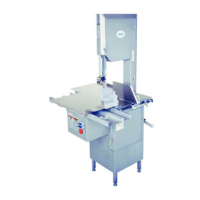
6. Place removable nger lift with saw guard assembly
(Part No. A14211) on the saw guide bar (Part No. 116-22)
and fasten in place with nger lift fastener knob
(Part No. 211A-291Q).
7. See Lower Removable Wheel Installation and Removal
Instructions for Model 1433 below.
FINGERLIFT
ASSEMBLY
REMOVAL and INSTALLATION
for Self-Centering Lower Removable Wheels
(Part No. 14560-1 and 14560DF-1)
ALWAYS Turn off, unplug Machine From Power Source and Perform Lockout/Tagout Procedure
to the Machine BEFORE Cleaning or Servicing.
Follow disassembly procedures in the Cleaning Section of the Operating and Service Manual.
Removal of the T-Handle and Lower Wheel will be the last 2 parts removed in the number sequence.
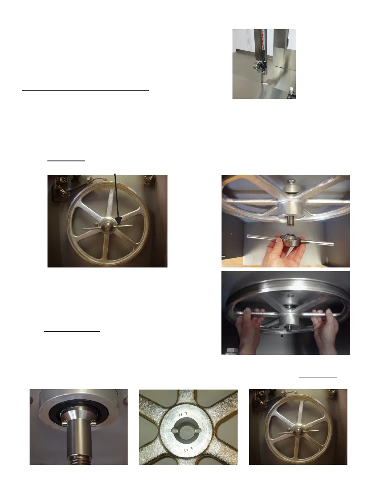
REMOVAL
Loosen Item No. 14746-1, T-Handle and Remove from Lower Shaft.
Using both hands @ 3 and 9 o-clock
Positions, Pull wheel towards you
with a even smooth motion.
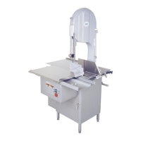
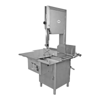
INSTALLATION
There is a anti-rotation pin located on the lower shaft,
there is a anti-rotation groove located on the back side
of the lower wheel.
Align and engage the groove of the lower wheel and the
anti-rotation pin as the wheel is being installed.
Install T-Handle Lock onto Lower
Shaft, Hand Tighten SECURELY