Step 6
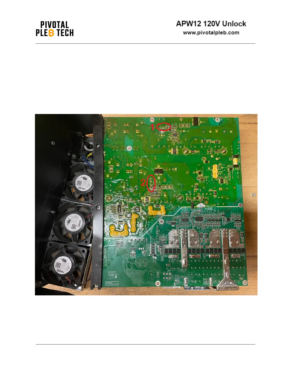
Locate both brown out detectors’ high-side resistor networks. Note that there are 2 sets
of three resistors in each network. The resistors are 0805 surface mount chip resistors
with a small, white “2204” label printed on top of each resistor. Also note that the white
silkscreen designators printed on the PCB next to each resistor may vary from PSU
variant to PSU variant. The silkscreen designators next to each resistor on the unit you
are modifying may not match the silkscreen designators in the images below.
Document Revision 3
2024-02-01 10