ST-150-4 37
All screw compressors
Analogue signal for capacity
control
0 .. 10VDC, ±2% at 100% with max. 1mA
or 4 .. 20mADC, ±2% at 100%, 500Ω resistor in parallel
linear control signal required
This type of control is particularly suitable for systems with simple controllers
equipped with an output for 0 to 10 V and with a relay.
Terminal strip CN14
All screw compressors
Modbus connection
0 .. 10VDC, linear control signal required
Modbus RTU, RS485, detailed description see BEST SOFTWARE.
Cables at L1, L2, L3 marking on the CM-SW-01 or at the fixed connectors located below
Operating recognition monitor-
ing, part-function of rotation dir-
ection monitoring
recognition range: 20 .. 135Hz at 83 .. 690V
time delay after activation of input signal of safety chain at CN2:3: 7s
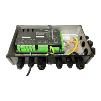
3.3.1 Voltage supply of the peripheral devices
The compressor module internally supplies voltage to
peripheral devices (solenoid valves, slider position in-
dicator, oil and oil filter monitoring and/or oil heater)
and to the terminal strips CN7 to CN12.
3.3.2 Rotation direction monitoring fuse (F08)
The HS. and CS. compressors incorporating the com-
pressor module are equipped with the F08 fuse in the
terminal box. It protects the rotation direction monitor-
ing lines between terminal box and module housing.
Such a fuse is also required with open compressors
between module housing and motor terminal box when
the rotation direction monitoring function of the com-
pressor module is used.
Technical data of the installed fuse:
• Rated current 1A
• Release speed FF (very quick acting)
• Rated breaking capacity of 50kA at 700VAC
• Dimensions 6.3 x 32 mm
3.4 Available cable bushings into the module housing
HS.95 Screwed joints:
1xM20x1.5 for 1 cable with a clamping range between Ø8 and 13mm
1xM16x1.5 for 1 cable with a clamping range between Ø5 and 10mm
OS.95 Screwed joints:
1xM20x1.5 for 1 cable with a clamping range between Ø8 and 13mm
1xM16x1.5 for 1 cable with a clamping range between Ø5 and 10mm
Blind caps: 1xM25x1.5 and 1xM16x1.5
OS.85 Screwed joints:
1xM20x1.5 for 1 cable with a clamping range between Ø8 and 13mm
1xM16x1.5 for 1 cable with a clamping range between Ø5 and 10mm
Blind caps: 1xM25x1.5, 1xM20x1.5 and 1xM16x1.5
Cable plugs for 2 cables of Ø7mm
CS.105 CS.105:
Screwed joint: 1xM20x1.5 for 1 cable with a clamping range between Ø8 and
13mm
Blind cap: 1xM16x1.5
Cable plugs for 2 cables of Ø7mm and 2 cables of Ø5mm
 Loading...