6 7
7. For positive-grounded vehicle, connect the negative (BLACK) clamp
from battery charger to the negative (NEG, N, –) ungrounded post of
battery. Connect POSITIVE (RED) clamp to vehicle chassis or engine
block away from battery. Do not connect clip to carburetor, fuel lines
or sheet-metal body parts. Connect to a heavy gauge metal part of the
frame or engine block.
8. When disconnecting charger, disconnect AC cord, remove clamp from
vehicle chassis, and then remove clamp from battery terminal.
9. See operating instructions for length of charge information.
CHARGING A BATTERY THAT HAS BEEN
REMOVED FROM A VEHICLE
WARNING – A spark near the battery may cause an explosion. To
reduce risk of a spark near the battery:
1. Check polarity of battery posts. The positive post (marked POS,P, +)
usually has a larger diameter than the negative battery post (marked
NEG, N, –).
2. Attach a 24-inch (minimum length) AWG #6 insulated battery cable to
the negative battery post (marked NEG, N, –).
3. Connect the positive (RED) charger clamp to the Positive battery post
(marked POS, P, + or red).
4. Stand as far back from the battery as possible, and do not face battery
when making final connection.
5. Carefully connect the negative (BLACK) charger clamp to the free end of
the battery cable connected to the negative terminal.
6. When disconnecting charger, always do so in reverse sequence of
connecting procedure and break first connection while as far away
from battery as practical.
Note: A marine (boat) battery must be removed and charged on shore. To charge it on board requires
equipment specifically designed for marine use. This unit is NOT designed for such use.
Check unit periodically for wear and tear. Return to manufacturer for
replacement of worn or defective parts immediately.
OPERATING INSTRUCTIONS
CHARGING THE BATTERY
WARNING: TO REDUCE THE RISK OF INJURY OR PROPERTY
DAMAGE:
• Always disconnect the AC plug from the AC outlet first before
disconnecting the charger from the battery to be charged.
• Ensure that all installation, operating instructions and safety
precautions are understood and observed; then follow the steps
outlined in the appropriate section (“Charging a battery installed
in a vehicle” or “Charging a battery that has been removed from a
vehicle”).
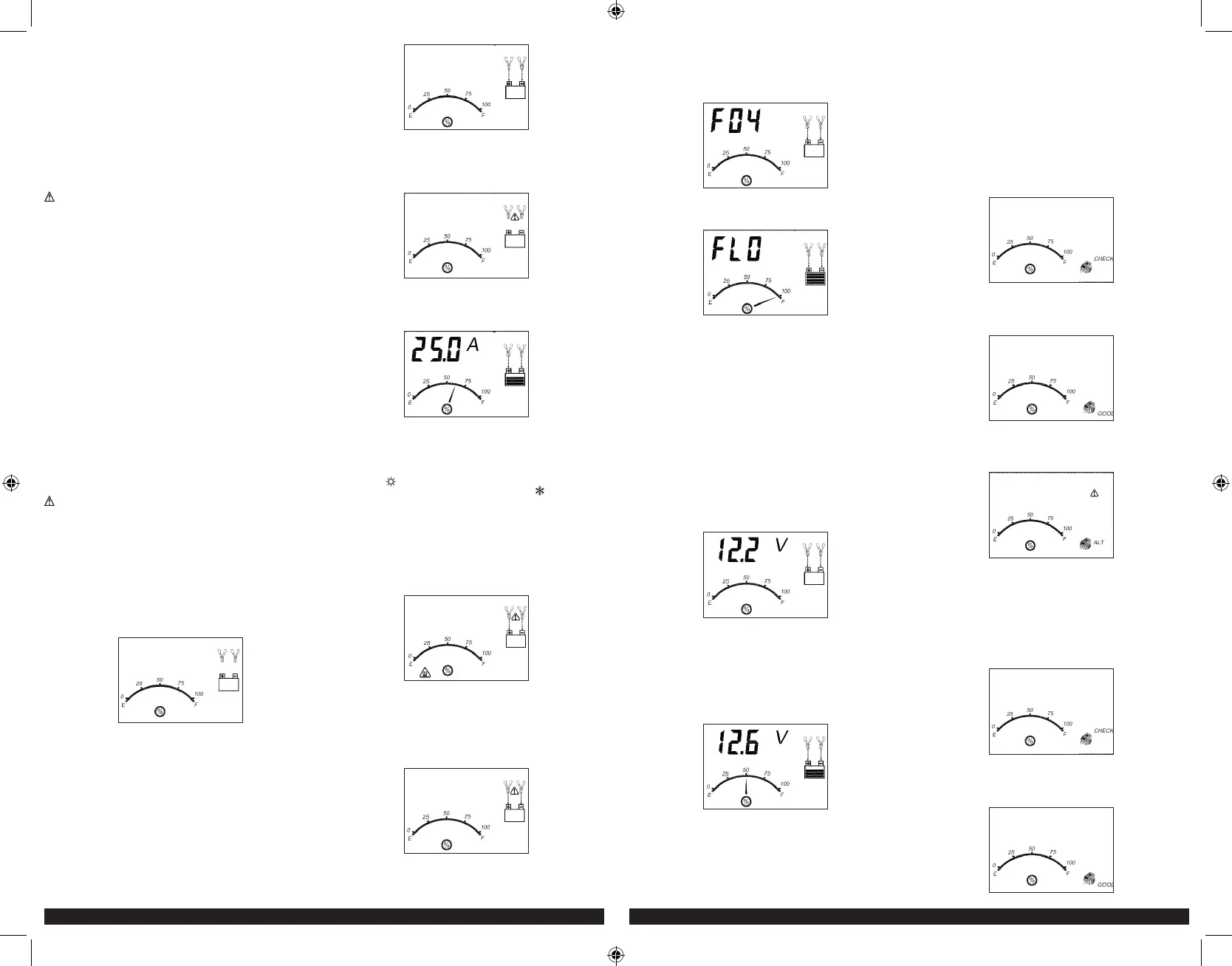
1. Plug the battery charger’s power cord into an AC outlet. The LCD screen
will display the following (the clamp icon will flash, the empty battery
icon and the gauge without the pointer will light):
2. The charger’s battery clamps are color-coded. Red is positive; black
is negative. Connect the battery clamps correctly to the corresponding
connectors on the battery posts following the steps outlined in the
“IMPORTANT SAFETY INSTRUCTION” section at the front of this manual.
Notes: If the clamps are correctly connected with regard to polarity and the unit is properly
connected to the AC outlet, the unit will be in Standby mode and the LCD screen will
display the following (the clamp icons, arrow icons, the battery icon and the gauge
without the pointer light solid):
If the clamps are INCORRECTLY connected with regard to polarity, the
LCD screen will display the following (the “+” and “–” inside the battery
icon and the fault icon will flash and the clamp icons, the battery icon
and the gauge without the pointer will light) and a warning will sound
until the clamps are disconnected:
Unplug the charger; then remove the clamps. Reconnect the clamps
properly.
3. When the unit is properly connected, press the battery charge button on
the control panel. The LCD screen will display the following:
The digital display shows the output current that is charging the battery.
The gauge indicates the charge status of the battery. The clamp icons
and the battery icon light solid, the bars on the battery icon will change
from empty to solid (bottom to top) repeatedly and the arrow icons will
gradually and repeatedly move downward to the battery icon.
Notes: The “ ” icon will appear at the top right of the gauge section if the surrounding
ambient temperature is higher than approximate 40°C. The “ ” icon will appear at
the top left of the gauge section if the surrounding ambient temperature is lower than
0°C. This is not a fault code, but indicates that the unit’s temperature compensation
feature is operating.
The charging process will start automatically approximately one minute
after the unit is properly connected.
Important: If the unit is overheated, the LCD screen will display the
following (the overheat alarm icon, fault icon and the battery icon will
flash; and the clamp icons, arrow icons and the gauge without the
pointer will light):
Disconnect the charger and allow the charger to cool for several
minutes. Make sure there is adequate ventilation around the unit before
attempting to charge again.
IMPORTANT: The charger will automatically detect the battery condition.
If it detects a problem with the battery, the LCD screen will display the
following (the fault icon and the battery icon will flash; and the clamp
icons, arrow icons and the gauge without the pointer will light):
Disconnect the charger. Have the battery checked by a qualified technician.
IMPORTANT: If the battery is not fully charged (the battery charge
gauge does not reach 100%) after 18 hours of continuous charging,
the battery may have internal damage and will not accept a charge.
After 18 hours, the charging process will automatically cut-off, the
LCD screen will display the following (the digital readout shows “F04”,
the clamp icons, arrow icons, battery icon and the gauge without the
pointer will light solid):
Disconnect the charger. Have the battery checked by a qualified technician.
4. When the battery is completely charged, the unit automatically goes
into float charge mode and the LCD screen displays the following:
5. The digital display shows “FLO” to indicate that the unit is in float
charge mode. The battery charge gauge points to 100%, indicating a
full charge. The clamp icon and battery icon with four bars light solid,
and the arrow icons will gradually and repeatedly move downward to
the battery icon. In this mode, the unit monitors the battery voltage and
charges as necessary to assure the battery maintains full capacity. The
unit remains in float charge mode as long as the charger is connected
to the battery and plugged into a functioning AC outlet.
When disconnecting charger, disconnect the AC cord, remove clamp from
vehicle chassis, and then remove clamp from battery terminal.
CHECKING THE BATTERY VOLTAGE
To check the battery voltage in standby mode
1. Set up the battery charger and connect to the battery following steps 1
through 2 in the “Charging the Battery” section.
2. Press the battery voltage check button. The LCD screen will display
the following:
3. The digital display shows the current voltage of the connected battery
for 10 seconds. During this period, pressing the battery voltage check
button again will return the unit to standby mode. The gauge without
the pointer will light solid. The unit will automatically return to standby
mode after 10 seconds.
To check the battery voltage in charging mode:
Press the battery voltage check button and the LCD screen will display
the following:
The digital display shows the current voltage of the connected battery
for 10 seconds. During this period, pressing the battery voltage check
button again will return the unit to charging mode. Pressing the
alternator check button or the battery recondition button will have no
effect. The unit will automatically return to charging mode after 10
seconds.
When disconnecting charger, disconnect AC cord, remove clamp from
vehicle chassis, and then remove clamp from battery terminal.
USING THE ALTERNATOR CHECK FUNCTION
Set up the battery charger and connect to the battery following steps 1
through 2 in the “Charging the Battery” section.
Part 1
No Load (turn OFF all vehicle’s accessories): The battery must be
fully charged before testing the alternator. Run the engine long enough to
achieve normal idle speed and verify there is a no-load voltage.
1. Press the alternator check button to start the check. The LCD screen
will display the following to indicate the unit is analyzing the alternator:
“Check” will flash, and the alternator icon and the gauge without the
pointer will light solid.
2. If the unit detects that the alternator is good, the LCD screen will
display the following:
“Good”, the alternator icon and the gauge without the pointer will light
solid.
3. If the unit detects that the alternator is out of typical voltage range, the
LCD screen will display the following:
The fault icon will flash; and the alternator icon, “ALT” and the gauge
without the pointer will light solid.
4. Press the alternator check button again to stop the test.
Part 2
Under Load (accessories ON): Next, load the alternator by turning on as
many accessories as possible (except for A/C and Defrost).
1. Press the alternator check button to start the check. The LCD screen
will display the following to indicate the unit is analyzing the alternator:
“Check” will flash, and the alternator icon and the gauge without the
pointer will light solid.
2. If the unit detects that the alternator is good, the LCD screen will
display the following:
BC15_25_40BD_ManualENSP_061920.indd 6-7BC15_25_40BD_ManualENSP_061920.indd 6-7 6/24/2020 2:58:26 PM6/24/2020 2:58:26 PM
 Loading...