11
CHAPTER 2: Introduction
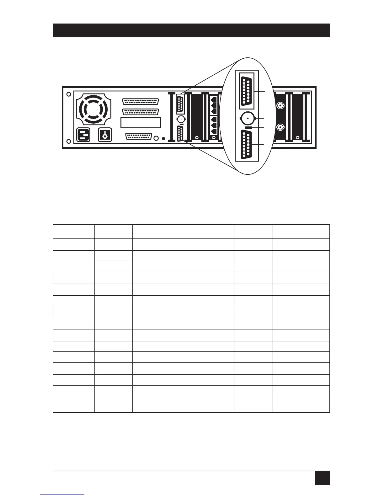
Figure 2-3. RISC Bridge/E Expansion Card Components.
Table 2-3. Port Pin Assignments for the DTE/MAU.
Contact Circuit Use DTE MAU
3 DO-A Data Out Circuit A Out In
10 DO-B Data Out Circuit B Out In
11 DO-S Data Out Circuit Shield Out In
5 DI-A Data In Circuit A In Out
12 DI-B Data In Circuit B In Out
4 DI-S Data In Circuit Shield In Out
8 CO-S Control Out Circuit Shield
2 CI-A Control In Circuit A In Out
9 CI-B Control In Circuit B In Out
1 CI-S Control In Circuit Shield In Out
6 VC Voltage Common Out In
13 VP Voltage Plus Out In
14 VS Voltage Shield Out In
Shell PG Protective Ground
(Conductive shell)