37
CHAPTER 3: Installation and Preconfiguration
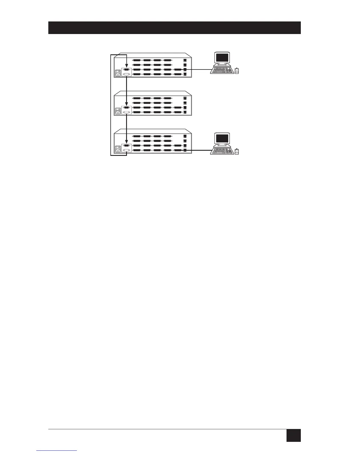
Figure 3-4. The ring topology.
Use a ring arrangement if you have user stations attached to two different Matrix
ServSwitches and you want both of the users to have access (or at least potential
access) to all CPUs. Run Expansion Cables from the OUT ports of each Switch to
the IN ports of the previous Switch in the chain, just like the bus topology, but
then add another cable from the OUT port of the first Switch to the IN port of the
last Switch. Because it interlinks the first and last Switches instead of making them
the endpoints, the ring configuration lets either user reach any CPU.
To use the ring topology, you’ll need to remove a jumper on two of your
Expansion Modules; see Section E.1 of Appendix E.
Cable runs from OUT on
Unit 3 to IN on Unit 2
Cable runs from OUT on
Unit 3 to IN on Unit 2
Cable runs from
OUT on Unit 1 to
IN on Unit 3
Unit 3:
CPUs 33 to 48
User B (KVM 2)
User A (KVM 1)
Unit 2:
CPUs 17 to 32
Unit 1:
CPUs 1 to 16