9
EN
ELECTRONICS OPERATION ALGORITHM
The fan with the T timer activates upon control voltage application to the LT input terminal by the external switch (e.g.
indoor light switch). After the control voltage is off, the fan continues to operate within the set time period adjustable from
2 to 30 minutes by the timer. For the ST model, the fan is turned on/off with an internal cord switch.
The fan with the timer and the humidity sensor H starts after the control voltage is supplied to the LT input terminal or
if the indoor humidity level H exceeds the set point adjustable from ~60 % to ~90 %. After the control voltage is off or the
humidity level has decreased, the fan will keep running within the time set by the timer ranging from 2 to 30 minutes. To set
the maximum humidity setpoint, set the potentiometer to H
max
position (90 %).
CAUTION! Connect the fans rated for 12 V power voltage (stated on the packing box and on the fan casing) to
12 V power mains only!
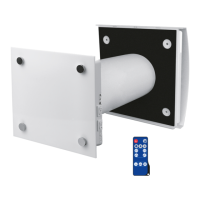
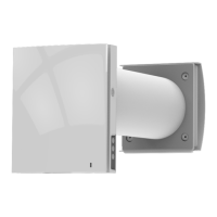
INSTALLATION AND SET-UP
The fan is designed for wall or ceiling mounting with direct air exhaust to the ventilation shaft or into the round air duct of
matching diameter (Fig. 2).
Fan installation sequence:
step 1. Cut off power supply and make sure electricity has been turned off (Fig. 6).
step 2. Run the power cable to the vent hole (Fig. 7).
step 3. Remove the front panel from the fan. Then remove the circuit board cover (Fig. 8).
step 4. Mark and drill holes for mounting the fan and then install the fan (Fig. 9-11).
step 5. Connect the fan to power mains according to the wiring diagram (Fig. 14-17).
step 6. Cover the casing with a front panel and a decorative panel (Fig. 12).
step 7. Supply power voltage to the fan (Fig. 13).
TERMINAL DESIGNATIONS ON WIRING DIAGRAMS
L — phase (220-240 V only) S — external switch
N — neutral (220-240 V only) QF — automatic circuit breaker
LT — timer control line