EasyManua.ls Logo

BLUELIGHT BL6-U - Page 8

BLUELIGHT BL6-U
58 pages
Print Icon
To Next Page IconTo Next Page
To Previous Page IconTo Previous Page
Loading...
BL6-U Parallel Integrated Controller Quick Commissioning User Manual
7
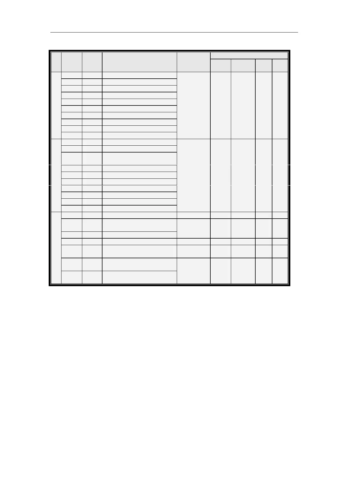
CHART 2.1 Control Circuit Port definition and Function ()
Port
No.
Terminal
Symbol
Location
Definition
Usage
Interface Tech Spec
Interface
Type
Rated
Capacity
On/off
Time
Max
Speed
J9
X16
J9-10
SSDZ top terminal input
Input
OC
DC24V
7mA
10mS
100Hz
X17
J9-9
SXDZ bottom terminal input
X18
J9-8
ARD input
X19
J9-7
SKM door open signal input 1
X20
J9-6
SGM door close signal input 1
X21
J9-5
SKMW1 door open limit input 1
X22
J9-4
SGMW1 door close limit input 1
X23
J9-3
STAB1 safe plate 1 input
X24
J9-2
SDS electronic lock signal input
X25
J9-1
SCZ over-load input
J10
X26
J10-10
SMZ full-load input
Input
OC
DC 24V
7mA
10mS
100Hz
X27
J10-9
Spare/ Re-leveling condition input
X28
J10-8
Light-load anti-nuisance input/
Rear door lock detection
X29
J10-7
SZH Attendant input
X30
J10-6
SZS Bypass drive input
X31
J10-5
Right brake feedback input
X32
J10-4
Thermal switch input
X33
J10-3
SKM2 door open input 2
X34
J10-2
SGM2 door close Input 2
X35
J10-1
Standby/ Re-leveling sensor input
J11
+24V1
J11-1
Input common terminal
24V_GND
J11-2,
J11-3
Input power ground
Power
Power
DC24V10A
+24V
J11-4
Input power
AG0 IN
J11-5
Analog input
Input
Analog
-10V~+10V
GND1
J11-6
Input ground
Analog input
ground
1H
J11-7
Duplex/Group control
communications +
Communication
Interface
CAN
80mA
25Khz
1L
J11-8
Duplex/Group control
communications -