Do you have a question about the BLUM ZX-Speed and is the answer not in the manual?
Defines important symbols like CAUTION! and NOTICE used in the manual for safety and damage avoidance.
Details critical hazards that can cause injuries if not avoided, emphasizing careful handling of the system.
Highlights measures to prevent material damage, particularly concerning aggressive liquids and short circuits.
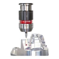
Illustrates and lists the main parts of the tool setting probe system.
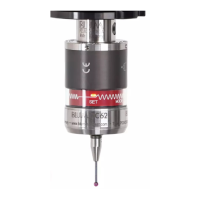
Explains the function of the LED indicator, including its states and meanings.
Provides detailed technical drawings with measurements for the probe and its mounting.
Lists key specifications such as protection class, power supply, measuring force, and operating temperatures.
Covers essential safety warnings related to voltage, compressed air, and proper tool usage during installation.
Details various mounting configurations for the probe, focusing on cable exit directions and requirements.
Instructions for mounting with the cable exiting to the side, including hose fixation and bending radius.
Instructions for mounting with the cable exiting downwards, emphasizing strain relief and bending radius.
Explains horizontal mounting, focusing on chip protection at the stylus and potential need for a cover.
Refers to installation instructions for mounting systems that incorporate a nozzle.
Details how to adjust the probe using a rounded washer to compensate for installation angle errors.
Describes the adjustment procedure for probes with side cable exit using a rounded washer.
Describes adjustment for downward cable exit, including O-ring checks and screw tightening.
Guides on pre-assembling the probe contact with the adapter, emphasizing correct torque and tool usage.
Provides instructions for mounting the probe contact, including tool usage, torque, and chip protection fixation.
Warns about potential damage from faulty mounting, short circuits, and chip interference during wiring, and connects cable shielding.
Illustrates the timing diagrams for the probe's status signals (X/Y, Z) and LED indicators.
Advises on limiting travel to prevent collisions and maintaining consistent feedrates for optimal measuring accuracy.
Provides step-by-step instructions for cleaning the probe, including part removal, cleaning methods, and post-cleaning checks.
Details the procedure for replacing the probe contact, including tool usage, torque specifications, and calibration.
Explains how to interpret error messages and provides initial troubleshooting steps for common issues.
Addresses problems where the probe fails to return to its rest position, suggesting checks on setscrews and tightening torque.
| Brand | BLUM |
|---|---|
| Model | ZX-Speed |
| Category | Measuring Instruments |
| Language | English |