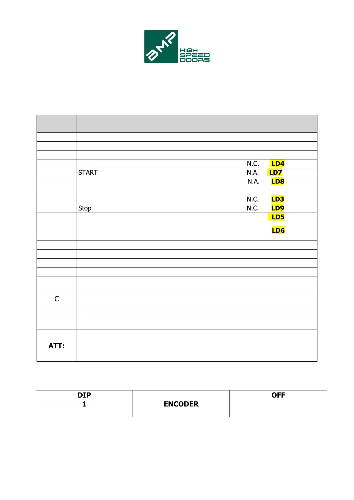
3. Terminals/connections
N°
1
2
3
9
11
12
13
14
16
19
N.C.
20
N.C.
23
24
25
26
27
28
29
30
31
FUNCTIONS DIP SW1
ON
UPS ENABLED UPS DISABLED
LIMIT SWITCH
2
Clamp CONNECTION
Power supply output +12Vdc
Power supply output 0 Vdc (-)
Communication serial
Anti-jamming sensor
Pedestrian Start (Opening with UPS)
Input common (+12Vdc)
Limit switch Open FCA/ Channel A (encoder)
Limit switch Closes FCC/ Channel B (encoder)
Photocell
Phase R Motor
Phase S Motor
Phase T Motor
Phase 230Vac line power supply
Neutral line power supply 230Vac
GND power supply
Common ashing dry contact
Dry contact output ashing
Brake(-) common
Brake(+) output
Jumper unused N.C. inputs
Max. accessory deliverable current: 500mA
3