8
J35
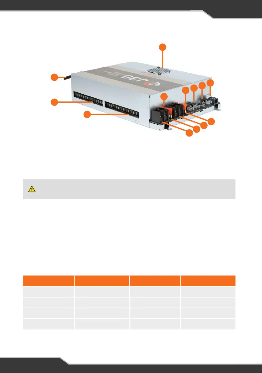
Figure 1: The J35
4
10
5
12
11
13
6
7
8
9
1
2
3
e LOAD TERMINAL BLOCK – POSITIVE CONNECTION
Positive wire connection point for the caravan’s 12V loads.
To control loads from the JHub App, each load must be connected to the correct
terminal. Terminals are labeled according to their designated load output.
w LOAD TERMINAL BLOCK – COMMON NEGATIVE CONNECTION
Negative wire connection point for the caravan’s 12V loads.
TERMINAL/LOAD CURRENT RATING TERMINAL/LOAD CURRENT RATING
1-Stereo 15A 5-Lights/Spare 10A
2-Spare 15A 6-Lights/Spare 10A
3-Pump 10A 7-Lights/Spare 10A
4-HWS 10A
Table 3: Designated terminal-load outputs for the load terminal block-positive connection, J35 Model
A.
q MAINS CABLE
The J35 is pre-cabled with a permanent mains power supply cord. The AC mains
input is protected by a quick acting, high breaking capacity type fuse (rated 250V,
10A).
Do not replace a damaged power supply cord. If the power cord is damaged, the J35 must be
discarded. Ensure that the AC mains source always has an earth terminal.