40
STEP
7B
Be careful to assemble all components
in the sequence they are presented.
1. See Diagram 2. Attach Pulley A3 (4) 4 ¼” Pulley and Pulley A5 (4) 4 ¼” Pulley as
shown using:
(2) 50 m10 x 215 hex head bolt
(4) 3 1 1/8” pulley spacer
(4) 60 m10 washer
(2) 70 m10 nylon lock nut
2. See Diagram 1. Feed the cable around Pulley A3 and back and through Upper Main
Frame D, then install Pulley A4 (4) 4 ¼” Pulley as shown in Diagram 2 using:
(1) 52 m10 x 95 hex head bolt
(2) 14 3/8” pulley spacer
(1) 70 m10 nylon lock nut
3. See Diagram 1. Route the Metal Ball End of the High Pulley Cable 90 forward and through
Press Arm Pivot Q and around Pulley A5 .
4. Then route cable back and through Upper Main Frame D and down through the support
arm sticking out of Upper Main Frame D. Then install Pulley A6 (4) 4 ¼” Pulley as
shown in Diagram 2 using:
(1) 54 m10 x 65 hex head bolt
(2) 48 5/16” bronze bushing
(1) 70 m10 nylon lock nut
5. See Diagram 3. Attach Press Arm Pulley Shroud U to Press Arm Pivot Q and tighten.
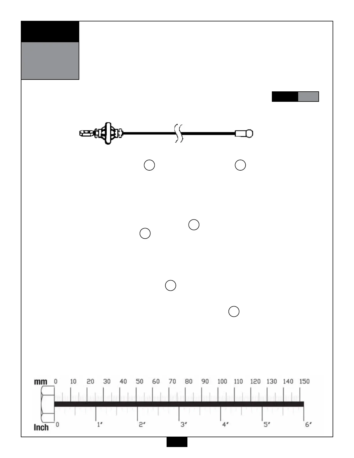
Ball Stop End Metal Ball End
High Pulley Cable (90)
NOTE:
Finger tighten all hardware in this step. Do Not wrench tighten until end of
STEP
8B