42
STEP
8A
Be careful to assemble all components
in the sequence they are presented.
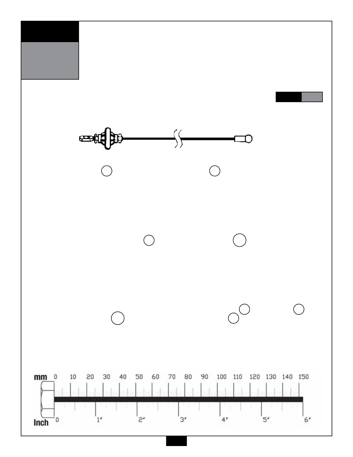
Ball Stop End Metal Ball End
High Pulley Cable (90)
1. See Diagram 1. Start at the Double Pulley Holder V and route the High Pulley Cable 90
around Pulley A7 (4) 4 ¼” Pulley and install Pulley A7 using:
(1) 54 m10 x 55 hex head bolt
(2) 60 m10 washer
(1) 70 m10 nylon lock nut
Route the High Pulley Cable 90 up and through the hole in the support arm in Upper Main
Frame D, then up and through the top of Upper Main Frame D, and then through the top of
Rear Upper Beam E and pull down the entire length of cable through.
2. See Diagram 2. Attach Pulley A8 (4) 4 ¼” Pulley and Pulley A10 (4) 4 ¼” Pulley as
shown using:
(1) 52 m10 x 95 hex head bolt
(1) 53 m10 x 45 hex head bolt
(2) 14 3/8” pulley spacer
(2) 60 m10 washer
(2) 70 m10 nylon lock nut
3. See Diagram 1. Make sure that the cable is routed above Pulley A8 , around Pulley A9
and above Pulley A10 . See Diagram 2. Attach Small Pulley A9 (15) 3 ½” Pulley as
shown using:
(1) 53 m10 x 45 hex head bolt
(2) 60 m10 washer
(1) 70 m10 nylon lock nut
NOTE:
Finger tighten all hardware in this step. Do Not wrench tighten until end of
STEP
8B