48
STEP
9B
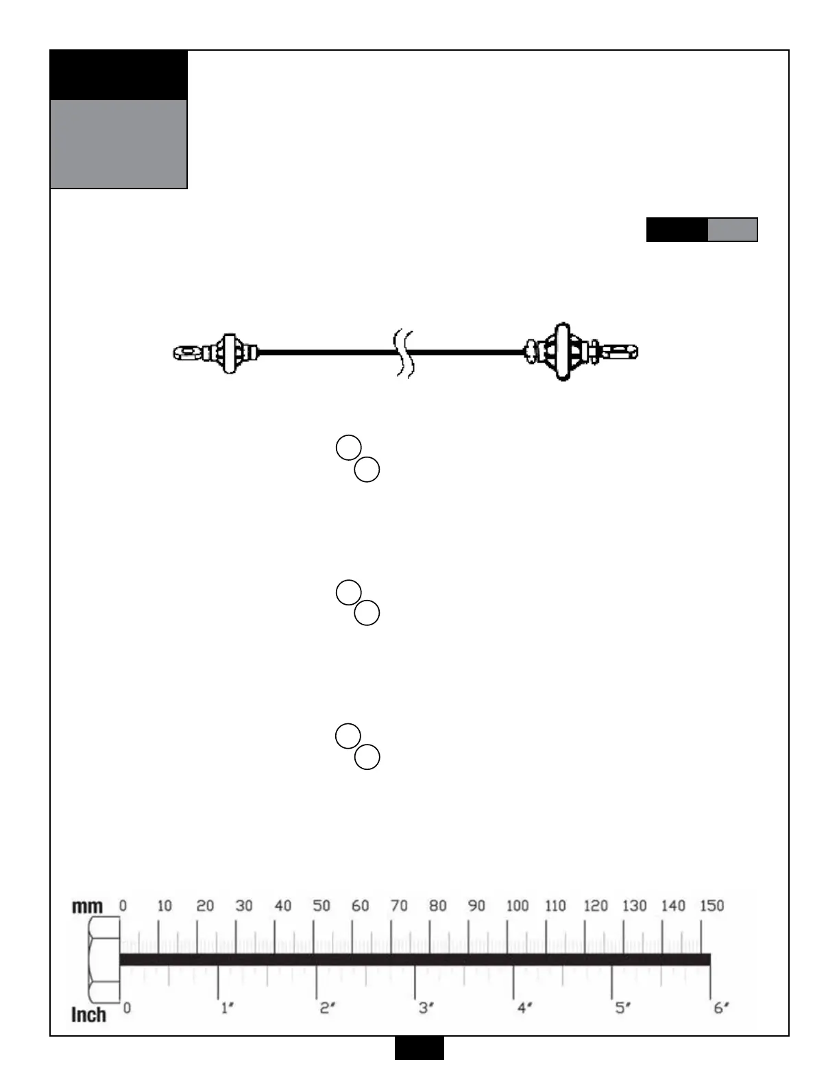
Small Ball End Ball Stop End
Low Pulley Cable (91)
1. See Diagram 1. Route the Low Pulley Cable 91 up and through the Double Pulley Holder V.
Route Cable 91 around Pulley B5 (4) 4 ¼” Pulley.
See Diagram 2 and install Pulley B5 (4) 4 ¼” Pulley as shown using:
(1) 54 m10 x 55 hex head bolt
(2) 60 m10 washer
(1) 70 m10 nylon lock nut
2. See Diagram 1. Route the Low Pulley Cable 91 down and through the Small Pulley Holder W.
Route Cable 91 around Pulley B6 (4) 4 ¼” Pulley.
See Diagram 2 and install Pulley B6 (4) 4 ¼” Pulley as shown using:
(1) 53 m10 x 45 hex head bolt
(2) 60 m10 washer
(1) 70 m10 nylon lock nut
3. See Diagram 1. Route the Low Pulley Cable 91 up and through Upper Main Frame D.
Route Cable 91 around Pulley B7 (15) 3 ½” Small Pulley.
See Diagram 2 and install Pulley B7 (15) 3 ½” Small Pulley as shown using:
(1) 52 m10 x 95 hex head bolt
(2) 14 3/8” pulley spacer
(1) 70 m10 nylon lock nut
NOTE:
Finger tighten all hardware in this step. Do Not wrench tighten until end of
STEP
10
Be careful to assemble all components
in the sequence they are presented.