22
STEP
2A
Be careful to assemble all components
in the sequence they are presented.
NOTE:
Finger tighten all hardware in this step. Do Not wrench tighten until end of
1. Attach Leg Extension Main Frame F to the 2” x 2” Front Stabilizer E using:
(1) a17 1/2” x 5 1/2” hex head bolt
(1) c1 1/2” washer
(1) b1 1/2” nylon locking nut
2. Attach Leg Extension Main Frame F to the 2” x 4” Upright D using:
(2) a1 1/2” x 5” hex head bolt
(2) c1 1/2” washer
(2) b1 1/2” nylon locking nut
3. Attach Leg Extension Frame J to the Leg Extension Main Frame F using:
(2)
(2)
(2)
(1)
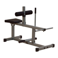
4. Slide (1) Foam Roller Bar Q into Leg Extension Frame J with (2) Foam Rollers d13
and (2) 1” Leg Ext Foam Roller End Cap d40 holding it in place as shown.
Attach (2) End Caps d28 onto the top and bottom Leg Extension Frame J and (1)
End Cap d28 onto the top of Leg Extension Main Frame F.
5. Slide (1) Foam Roller Bar Q into Leg Ext. Seat Pad Frame I with (2) Foam Rollers d13
and (2) 1” Leg Ext Foam Roller End Cap d40 holding it in place as shown.
Attach (3) End Caps d3 onto the Leg Ext. Seat Pad Frame I.
STEP
3B
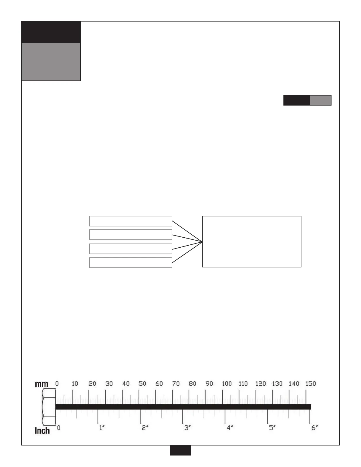
This hardware is attached
to Leg Extension Frame J
and shown in diagram
with a box around it.
M8 washer
M8 x 15mm round bolt
32 X 12 bearing
M12 X 75mm shaft