BOGE Operating instructions for C 10 L...C 20 L series screw compressors Page 11
Product description 2.2 Function description
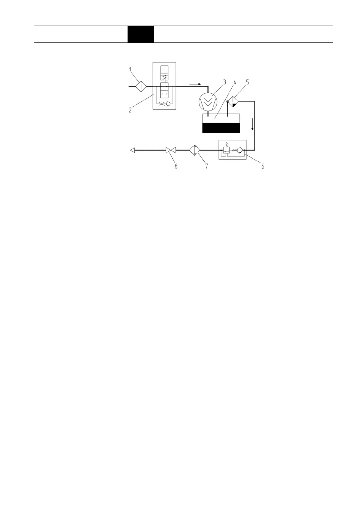
Air circuit
Fig. 2.1: Components of the air circuit
1 Intake filter
The intake filter cleans the air suctioned by the air end.
2 Intake regulator
The intake regulator opens (load operation) or closes (idling operation or
standstill) the suction line depending on the operating condition of the
compressor.
3 Air end
The air end compresses the sucked in air.
4 Compressed air/oil receiver
The compressed air separates from the oil under the force of gravity in the
compressed air/oil receiver.
5 Oil separator
The oil separator separates the residual oil contained in the compressed
air.
6 Minimum pressure check valve
The minimum pressure check valve does not open until the system pres-
sure has increased to 51 psig. This causes a rapid build-up of the system
pressure and ensures lubrication in the starting phase. Once the com
-
pressor has been switched off, the check valve prevents the compressed
air from flowing back out of the mains line.
7* Compressed air after-cooler (air cooled)
The compressed air is cooled in the compressed air after-cooler, causing
the water contained in the air to condensate.
8 Stop valve
The screw compressor may be isolated from the mains by means of the
stop valve.
* Optionally for receiver systems without refrigeration compressed air dry-
ers
 Loading...