Fliess.pm6.5 - USA
Page 6.1
Appendix
BOGE Operating instructions for S 40-2...S 341 / SF 40-2...SF 220 series screw compressors
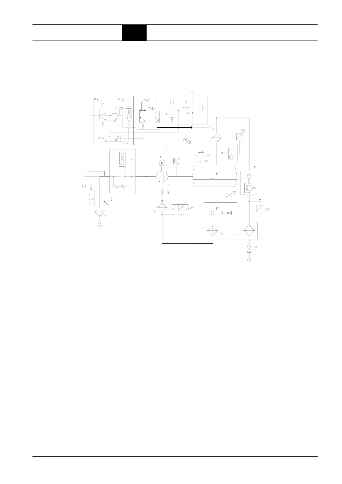
6.1 Flow chart
Air cooled version, standard
Air IN
Compressed air
OUT
1 = Suction filter
2 = Maintenance display (from 30 kW)
3 = Vacuum switch
(for suction filter monitoring) *
4 = Suction controller
5 = Ventilation and regulation control valve
7 = Drive motor
8 = Compressor air end
9 = Sensor for final compression temperature
10 = Combined compressed air/oil receiver
11 = Oil separator
12 = Safety valve
16 = Thermostatic oil control valve
17 = Oil cooler
18 = Oil filter
19 = Differential pressure switch
(for oil filter monitoring) *
20 = Oil throttle
21 = Minimum pressure check valve
22 = Compressed air after-cooler
23 = Pressure sensor system pressure
24 = Pressure sensor network pressure
25 = Stop valve, compressed air outlet
27 = Stop valve, oil drainage
28 = Check valve drainage line (up to 75 kW)
29 = Proportional controller *
30 = Diff. pressure switch for prop. controller *
31 = 3/2-way solenoid valve for prop. contr. *
(with standard control passage here)
37 = Display of F.a.d. for prop. controller *
42 = 3/2-way solenoid valve for suction control
regulation *
43 = Double check valve*
(Pos. 42 + 43 = rapid-start valve)
44 = Double check valve *
(Monitoring of rotational direction)
* = Option