All output wiring connections are made to the terminal strip located under the right
side access panel. Loosen the two Phillips-head screws on each side of the cover
and remove the cover.
IMPORTANT: Before making any connections or wiring changes to the amplifier
or any equipment connected to the amplifier, make sure that the amplifier is NOT
plugged into an AC outlet.
NOTE:
The amplifier does not have a power switch, so it must be unplugged in
order to turn the power off.
Speaker Connection The TPU35B, TPU60B, and TPU100B feature output connectors for 16-ohm, 25V,
25VCT and 70V speakers. The TPU250 provides outputs for 25V and 70V
speakers.
70-volt speaker connections are made between the 70V and COM terminals on
the output terminal strip. The COM and GND terminals of the output terminal strip
are connected using a shorting clip. The shorting clip enables the amplifier output
to act as an unbalanced output (one side of the output connected to ground).
If desired, the output can be made to be a balanced output with no connection to
ground. To balance the output, simply remove the shorting clip. All speaker
connections remain the same as above. 25V Speaker connections are done in the
same manner.
8
Output Wiring Connections
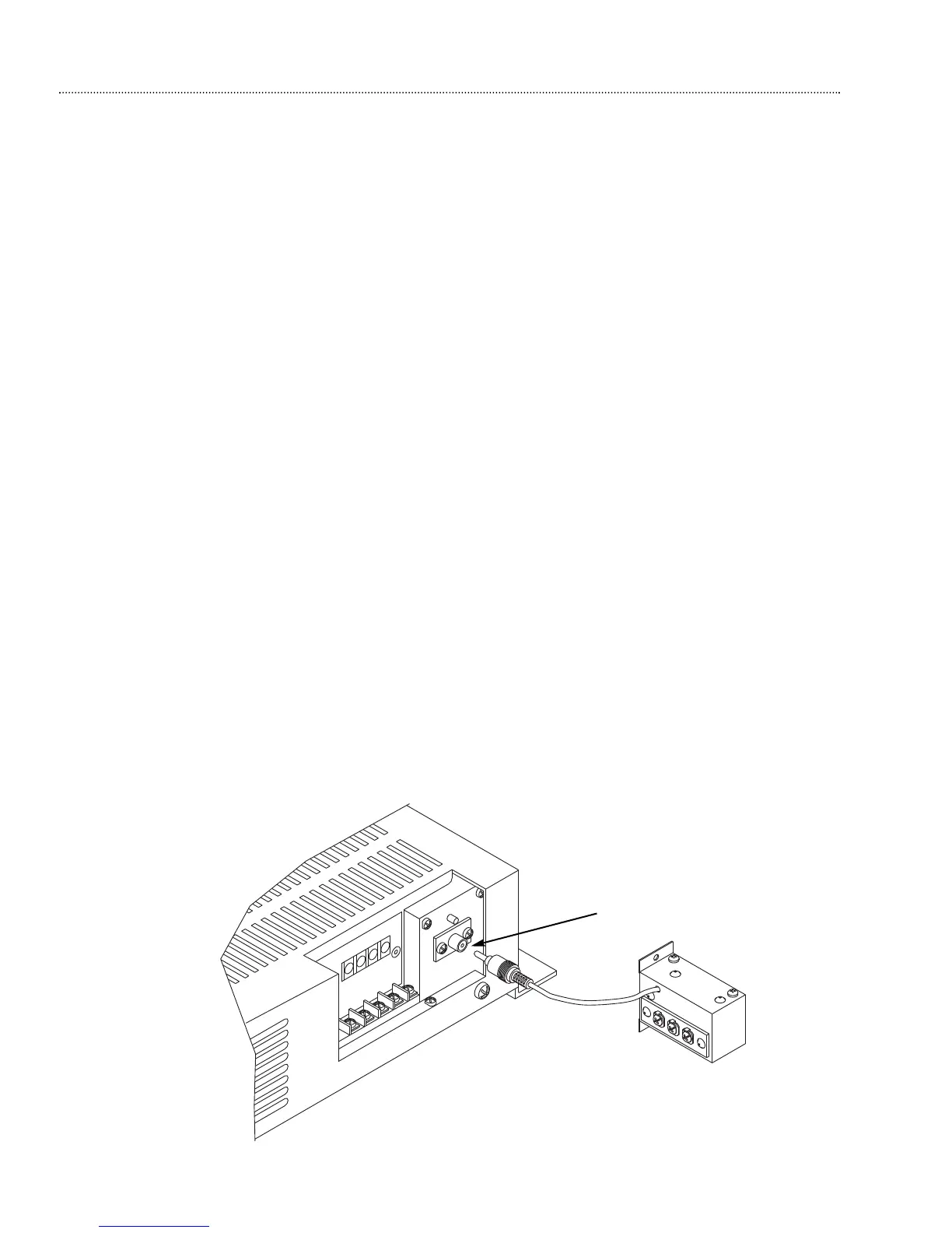
An RCA jack is provided near the output terminal strip for connection to a
WMT1A line-matching transformer. A 600-ohm, balanced telephone-level output
signal can be obtained by plugging the RCA connector of the WMT1A line-
matching transformer into this jack and taking the output signal off of the WMT1A
line-matching transformer screw terminals (see Fig. 6). The WMT1A will provide
approx. 1.73V output. This is useful for driving a long line when connecting to
remote equipment.
Output Cover Replacement When all output connections are made, remove the appropriate knockout on the
output cover. Replace the cover and tighten the screws while dressing the wires
through the knockout hole.