8
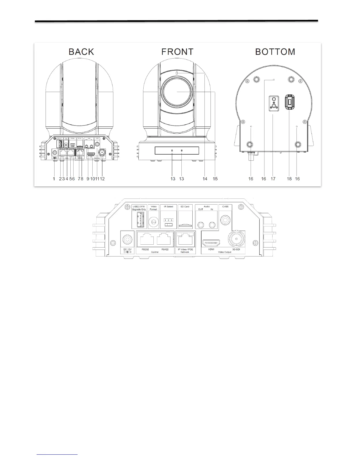
Camera Diagrams
1. 12V DC Power Port
Connect the supplied DC power adaptor and cord.
2. USB2.0 Port
For firmware upgrade only
3. RS232 Control Port (RJ45)
RJ45 to RS232 convertor cable is provided.
4. Video Format Selector
For video format selection
5. RS-422 Control Port (RJ45)
RJ45 to RS422 convertor cable is provided.
6. IR Remote ID Selector
Camera ID for IR remote controller
7. Micro SD Card Port
8. IP Network RJ45 Port
For VISCA over IP control and IP video streaming, with POE+(IEEE802.3at).
9. Audio Output/Input
10. HDMI Port (HDMI 1.4)
11. CVBS Video Output
12. 3G-SDI Video Output
13. IR Remote Controller Sensors
These are sensors to receive commands from infrared remote controller.
14. Power LED Indicator
Turns green when the camera is connected to power outlet. When the power is turned on, it takes about 15 to 30
seconds to display the image after LED turns on.
15. Lens