11
Stationary spray pipes have been used on F-series pumps Ref. Fig 5. It consists of a fixture frame (1), steel
pipe (2) and spray nozzle (3), it makes cooling fluid spray to piston and liner. Adjust cooling water supply
to the manifold and inspect spray nozzle operation very often to make sure the nozzle is pointed directly at
the piston.
Fig. 5
(1) Fixing frame (2) Steel pipe (3) Spray Nozzle (4) Soft pipe
Cooling fluid is transfused from spray pump (No.3 in Fig .7) through Water tank (No.5. in Fig. 7) to the
manifold on left/right wall plate of the frame. Adjust regulating valve (No.4 in Fig .7) to supply as
much water as possible to the liners without splashing back on the crosshead extension rods. Avoid
some water will work back into the power end to contaminate the lubrication oil.
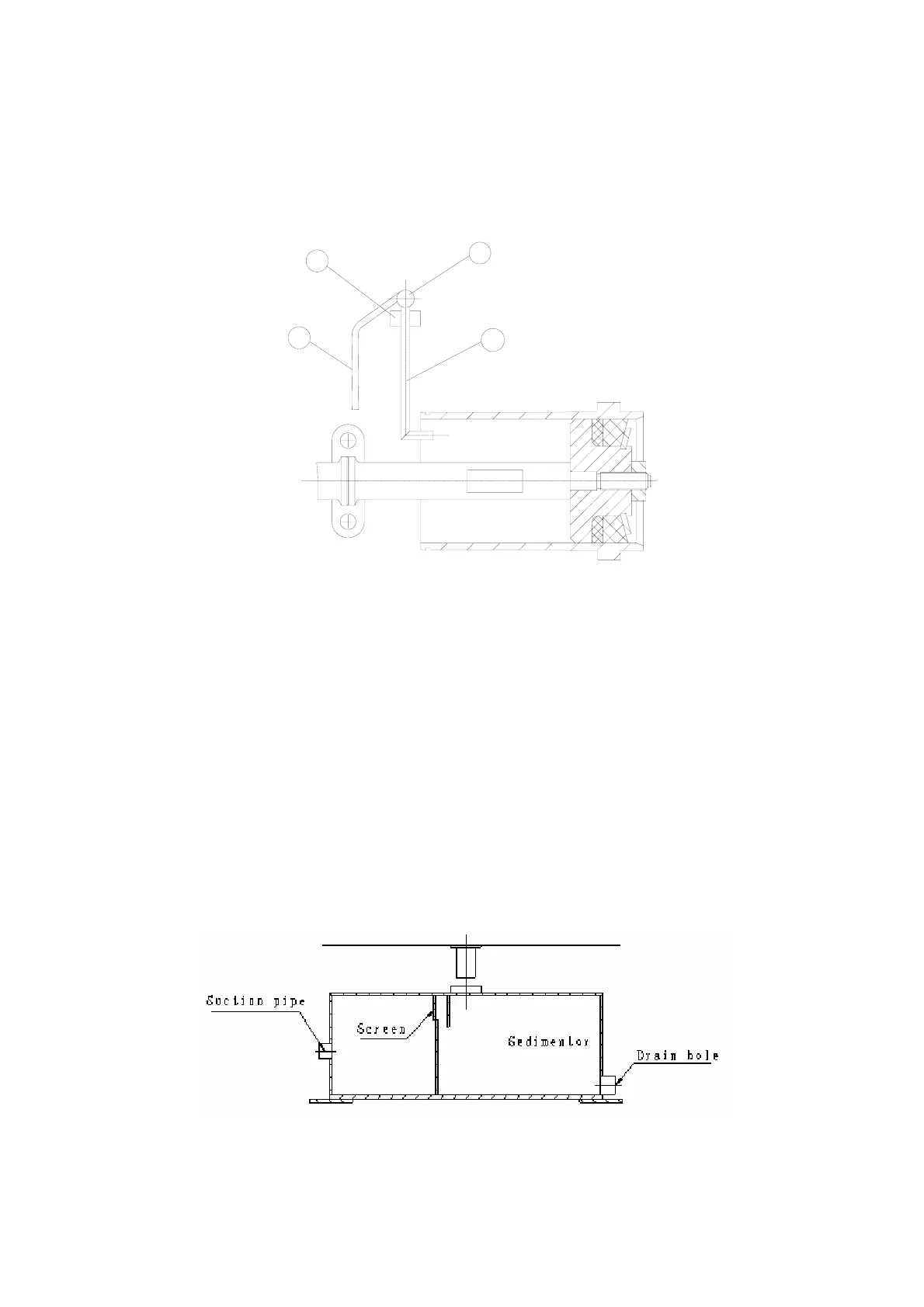
The cooling fluid returns to the setting chamber from the crosshead extension rod compartment, and
as the fluid overflows through the filter screen between the two sections of the tank, the solids are
allowed to settle out. The filter screen will catch much of the foreign material in the fluid. Refer to
Fig .6.
Check cleanliness of the cooling fluid at frequent intervals and CLEAN and FLUSH reservoir and
replace the cooling fluid as required. Increasing sand grain in contaminated fluid will cause premature
abrasion of liner and piston or stoppage of the spray nozzle or spray tube.
Fig. 6
2
1
4
3