Instruction Manual for F1300/1600 Mud Pump
31
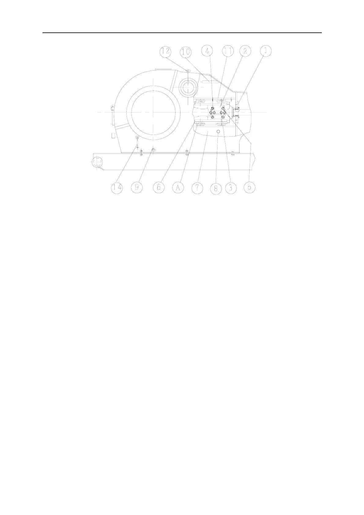
Fig.21
(1) Mud guard (2) Crosshead pin retainer (3) Bolt (4) Bolt (5) Jack screw bore (6) Lower guide (7)
Frame (8) Dirt discharge bore (9) Pipe plug (10) Oil accumulating box (11) Upper guide (12) Air shield
(14) Oil level gauge
Strike gently the crosshead large end into cone bore, fasten retainer bolt (3) and (4) (see Fig.21) with
torque 225~240 N.m (165~175ft. 1bs) and wire.
USE TORQUE WRENCH AND DO NOT EXCEED THE SETTING VALUES..
NOTE: To pull out the crosshead pin, first remove the four crosshead retainer bolts (4)
and screw two of the bolts into the “jack screw” holes (5). Tighten the two jack screw
bolts until the pin breaks loose. Complete removal of crosshead pin retainer plate (2) and
slide pin out of bore.
5) Check running clearance of crosshead by sliding long “feeler” gauges between crosshead upper
surface and guide. The clearance should be in 0.45-0.56mm (0.018-0.022in). Check with long feeler
gauge over entire surface of crosshead.
NOTE: Over tightening the crosshead pin retainer bolts (4) will cause crosshead outer
race contact circular arc deformation and increase the possibility of worn. Now loosen pin
and retighten into place by using the make-up torques shown in item 4) above.
3.8 Checking Crosshead Alignment
In order for the pistons to run normally in the liners, the crosshead must travel in a straight line along
the horizontal centerline of the frame bore. To check and adjust crosshead alignment, proceed as
follows:
1) Remove diaphragm stuffing box from the diaphragm plate, (Fig, 21). Do not remove the plate.
2) Position crosshead at the extreme front of its stroke. With inside calipers or telescoping gauges,
accurately measure the distance from the diaphragm plate bore to the crosshead extension rod at the
top and bottom. Compare the two measurements to determine the position of the rod relative to the
centerline of the bore.