Installation 31/60
RE 92100-01-B/09.2012, A4VSG Series 10, 11 and 30, Bosch Rexroth AG
Table 9: Above-reservoir installation
Installation position Filling / air bleeding housing
7 (drive shaft, horizontal) R(L)
8 (drive shaft, horizontal) T; R(L) plug
9 (drive shaft, horizontal) K
2
; R(L) plug
10 (drive shaft, horizontal) K
3
; R(L) plug
11 (drive shaft, vertically downward) R(L)
12 (drive shaft vertically upward) T; R(L) plug
7.4 Installing the axial piston unit
7.4.1 Preparation
1. Compare the material number and designation (ordering code) with the details in
the order confirmation.
If the material number for the axial piston unit does not correspond to the one in
the order confirmation, contact Bosch Rexroth Service for clarification, see
chapter10.5 "Spare parts" on page50.
2. Before installing, completely empty the axial piston unit to prevent any mixing
with the hydraulic fluid used in the machine/system.
L
R
W
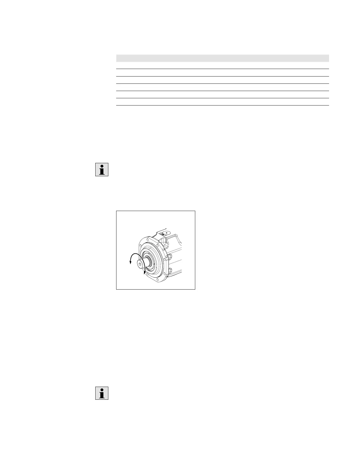
Fig. 10: Direction of rotation
W
1)
Bi-directional (counter-clockwise and clockwise rotation permissible)
L
Counter-clockwise
R
Clockwise
1)
In some cases, no alternating direction of rotation is possible. Please note separate data sheets
for controls, see Table 1 "Required and supplementary documentation" on page5.
3. Check the direction of rotation of the axial piston unit (on the name plate) and
make sure that this corresponds to the direction of rotation of the output/drive
shaft of the machine/system.
The direction of rotation as specified on the name plate determines the direction
of rotation of the axial piston unit as viewed on the drive shaft, see chapter5.3
"Product identification" on page20.