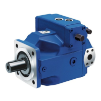
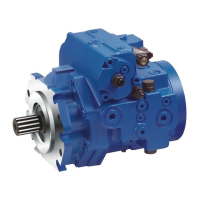
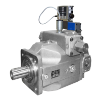
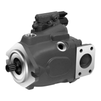
Do you have a question about the Bosch REXROTH A4VSG and is the answer not in the manual?
Defines the product's intended applications and lists impermissible uses.
Provides essential safety guidelines applicable to all operations.
Details safety warnings specific to the axial piston unit and HS5E control.
Outlines necessary personal protective equipment for safe handling and operation.
Explains control structures, parameters, modes, and working pressure limits for the HS5E system.
Outlines the correct sequence for switching on the electronics and hydraulics.
Details the crucial steps for making hydraulic and electrical connections to the unit.
Details setting pressure sensors, torque limitation, swivel angle, and pump/motor values.
Explains how to adjust controller parameters for specific plant requirements.
Guides users on how to systematically approach and diagnose faults in the system.
Explains how to access and interpret the internal error and diagnosis memory for fault analysis.
Provides comprehensive lists of malfunctions, their causes, and recommended remedies for unit and control system.
| Category | Water Pump |
|---|---|
| Series | A4VSG |
| Nominal Pressure (bar) | 350 |
| Type | Axial piston variable pump |
| Control Options | Hydraulic |
| Port Connection | SAE flange ports |

