16 | Commissioning
AGS10-2, AGS10E-2, AGS20-2, AGS50-26 720 811 270 (2015/04)
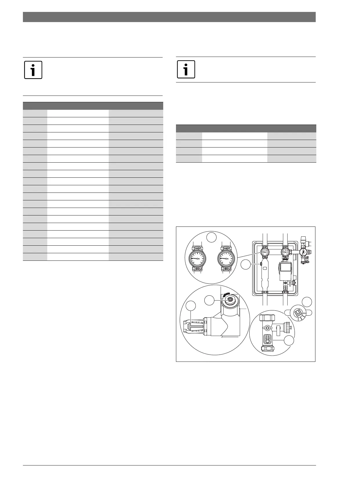
6.3.2 Checking the flow rate
▶ Refer to Tab. 13 for the required flow rate (at 30-40 °C in the return).
▶
Check the flow rate in the sight glass of the flow limiter (
Fig.
27
[3]).
6.3.3 Setting the flow rate
It may be necessary to reduce the flow rate for solar systems with up to
4 flat plate collectors (or 3 evacuated tube collectors).
▶ Set the speed to 100 % on the solar controller ( controller
instructions: "Function test").
If the maximum flow rate ( Tab. 14) is exceeded:
▶ Reduce the flow rate at the flow limiter [2] until the flow rate drops
below the maximum.
After commissioning
The viscosity of the heat transfer fluid makes air bubbles substantially
more resilient than those in pure water.
▶ After several hours of solar pump operation, vent the solar system via
the air separator in the solar pump station [4] and (if installed) the air
vent on the roof.
Fig. 27
[1] Gravity brake ready for operation
[2] Adjusting screw on the flow limiter, depending on the type
[3] Read-off edge for the flow rate, depending on the type
[4] Ventilation at the air separator
If the pre-set flow rate is not reached at the pump's
highest speed stage:
▶ Check maximum permitted pipe lengths and sizing
( Chapter 4.1).
▶ If necessary, install a more powerful solar pump.
Quantity Flat plate l/min
1)
1) Nominal flow rate per collector: 50 l/h
Evacuated tube l/min
2)
2) Nominal flow rate per collector: 30 l/h
1 1 0.5-0.6
2 1.5-2 1-1.2
3 2.5-3 1.4-1.8
4 3-4 1.9-2.4
5 4-5 2.4-3.0
6 5-6 2.9-3.6
7 5.5-7 3.3-4.2
8 6.5-8 3.8-4.8
9 7.5-9 4.3-5.4
10 8-10 4.8-6.0
11 9-11 5.2-6.6
12 10-12 5.7-7.2
13 10.5-13 6.2-7.8
14 11.5-14 6.7-8.4
15 12.5-15 7.1-9.0
16 13-16 7.6-9.6
17 14-17 8.1-10.2
18 15-18 8.6-10.8
19 15.5-19 9.0-11.4
20 16.5-20 9.5-12.0
Table 13 Maximum flow rate at 30 - 40 °C in the return depending on
collector version and number of collectors
Low energy pumps do not require a step switch as they
are modulated using a control signal.
Quantity Flat plate l/min Evacuated tube l/min
1 2.5 --
2 5 5
3 7.5 7.5
4 10 10
Table 14 Flow rate (maximum flow rate) at 30 - 40 °C in the return
depending on collector version and number of collectors
0,5
7
6
5
4
3
2
1
L/min
7
6
5
4
1
0,5
3
2
6720801165.19-2.ST
1
20
0
40
60
°C
80
100
120
20
0
40
60
°C
80
100
120
S E
3
2
4