AutoDome Modular Camera System Installing Roof Parapet and Pipe Mounts | en 31
Bosch Security Systems, Inc. Installation Manual F01U010921 | 1.0 | 2006.10
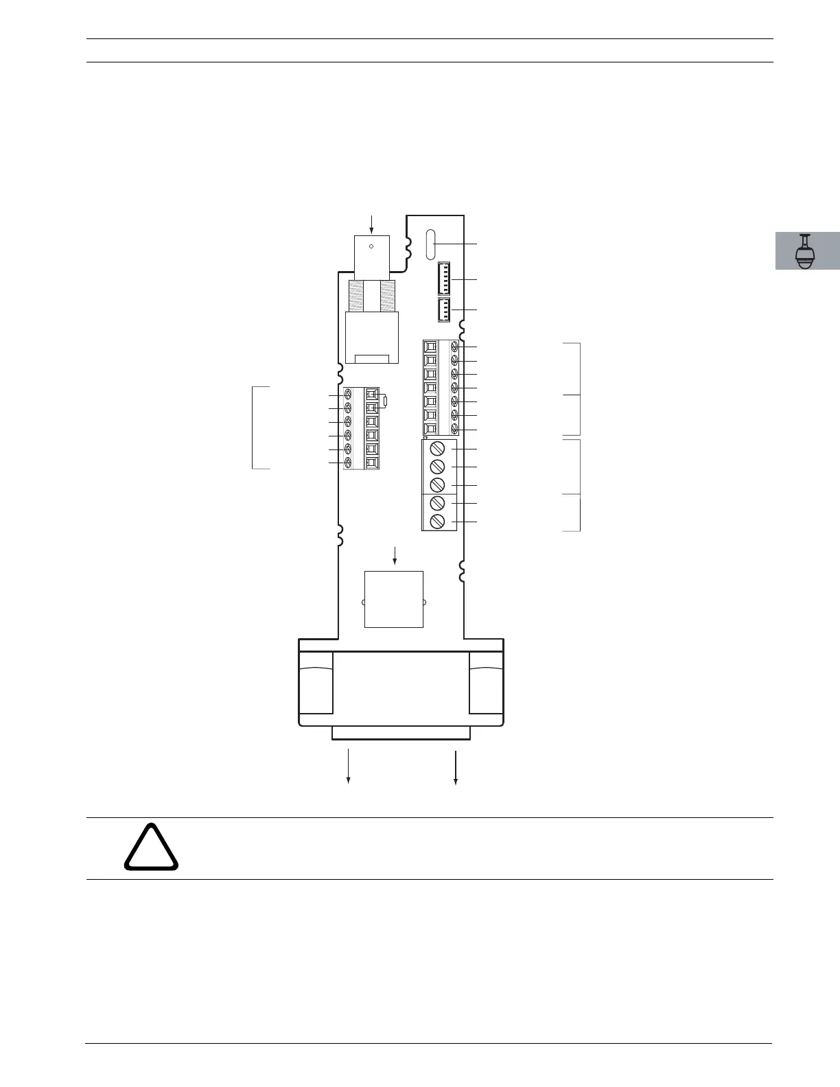
2.7 Wire Pipe Interface Board
This section provides instructions for connecting wires and cables to the Pipe Interface Board,
as illustrated below. See Chapter 4: Cable and Wire Standards for cable and wiring recommen-
dations and specifications.
Fig. 2.12 Pipe Interface Board Connections
VIDEO
COAX
IN
BNC
HEATER POWER
DOME POWER
ALARMS IN
(EoLR Supervised)
(1 -2)
RELAY OUTPUT
DATA
IN/OUT
RJ45
Ethernet
or UTP Video
TO AUTODOME
GND
4
ND
4 ALARM #
3 ALA
M #5
1 ALA
M #3
5 ALA
M #
7 GND
5 ALARM #1
6 ALARM #2
4 EARTH GROUND
3 N.C.
2 COM
1 N.O.
2 EARTH GROUND
1 DOME 24VAC
2 HEATER 24VAC
1 HEATER 24VAC
3 DOME 24VAC
- BIPHASE 1
+ BIPHASE 2
EARTH GROUND 3
- RxD 4
+ TxD 5
SIGNAL GND 6
WIRE GAUGE CHART
#1: AWG 26-16
#2: AWG 26-16
#3: AWG 18-14
J102
P105
P107 P101
P102 P103
P104
P106
J101
#1
#3
#2
4-PIN CONNECTOR
ALARMS OUT (1 - 3)
6-PIN CONNECTOR
ALARMS IN (3 - 7)
CABLE TIE SLOT
!
WARNING! 24 VAC Class II power supply only.
 Loading...