EasyManua.ls Logo

Bosch Blue Line Q1 User Manual

Bosch Blue Line Q1
10 pages
To Next Page IconTo Next Page
Page #1 background imageLoading...
Page #1 background image
© 2004 Bosch Security Systems
4998153066B
Page 1 of 10
2
3
4
Blue Line Q1
2-1
2-2
2-3
2-4
2-5
2-6
4-1
4-2
4-3
Blue Line Q1 Quad Passive Infrared Detector Installation Instructions .............................................................Page 3
Gebruiksaanwijzing voor de installatie van de Blue Line Q1 Quad passieve infrarood detector ...................Pagina 4
Blue Line Q1 Notice d’installation du détecteur à infrarouge passif Quad ...................................................... Page 5
Blue Line Q1 Passiver Quad-Infrarotmelder Installationsanleitungen ..............................................................Seite 6
Istruzioni di installazione del rilevatore a infrarossi passivi Quad Blue Line Q1 ............................................Pagina 7
Instruções de instalação do detector Quad por infravermelhos passivos Blue Line Q1 ...............................Página 8
Instrucciones de instalación del detector quad por infrarrojos pasivos Blue Line Q1 ...................................Página 9
Blue Line Q1 ಯ㢃㹿ࡼ㑶໪㒓᥶⌟఼ᅝ㺙䇈ᯢ.............................................................................................. ㄀义
3-2
7.5
3-3
0 ft
35200 ft 10 30
0 m
2,3
0 m 10,73,1 6,1 9,1
1.5
5
10 3,1
0 ft
35
5
20
17.5
15
0 ft 10
17.5
30
0 m
5,3
5,3
3-1
0 m 10,7
3,1
6,1 9,1
1,5
1,5
10
5
4,6
4,6
15
10
3,1
3,1
4-5
4-6
4-4
4-4
4-12
4-4
4-44-4
4-12
4-12
4-4
4-8
4-13
4-11
4-7
4-10
4-9 4-9
Question and Answer IconNeed help?

Do you have a question about the Bosch Blue Line Q1 and is the answer not in the manual?
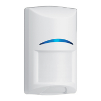
Bosch Blue Line Q1 Specifications

General IconGeneral
Coverage PatternCurtain
Current Consumption12 mA
Operating Temperature-10°C to +55°C
Detection Range12 m
Alarm RelayNormally Closed (NC)
Tamper RelayNormally Closed (NC)

Summary

Specifications

Installation Considerations

Coverage Patterns

Top View Coverage

Diagram illustrating the detector's coverage pattern from a top-down perspective.

Side View Coverage

Diagram showing the detector's coverage pattern from a side perspective.

Optional Look-down Zone

Description of how to create an optional downward detection area.

Mounting Instructions

Surface and Corner Mounting

Details for mounting the detector base using screws on surfaces or corners.

Optional Mounting Brackets

Information on using optional B335, B328, and B338 brackets for mounting.

Wall Tamper Wiring

Instructions for installing the wall tamper function with screws.

Wire Routing and Strain Relief

Guidance on threading wires through knockouts and using cable ties.

Terminal Block Wiring

LED Operation Settings

LED Jumper Configuration

Instructions for setting the LED jumper to enable or disable the indicator.

Creating Look-down Area

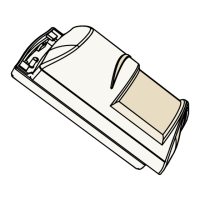
Method to create a look-down zone by modifying the lens cover tape.

Walk Test Procedure

Related product manuals