8
y
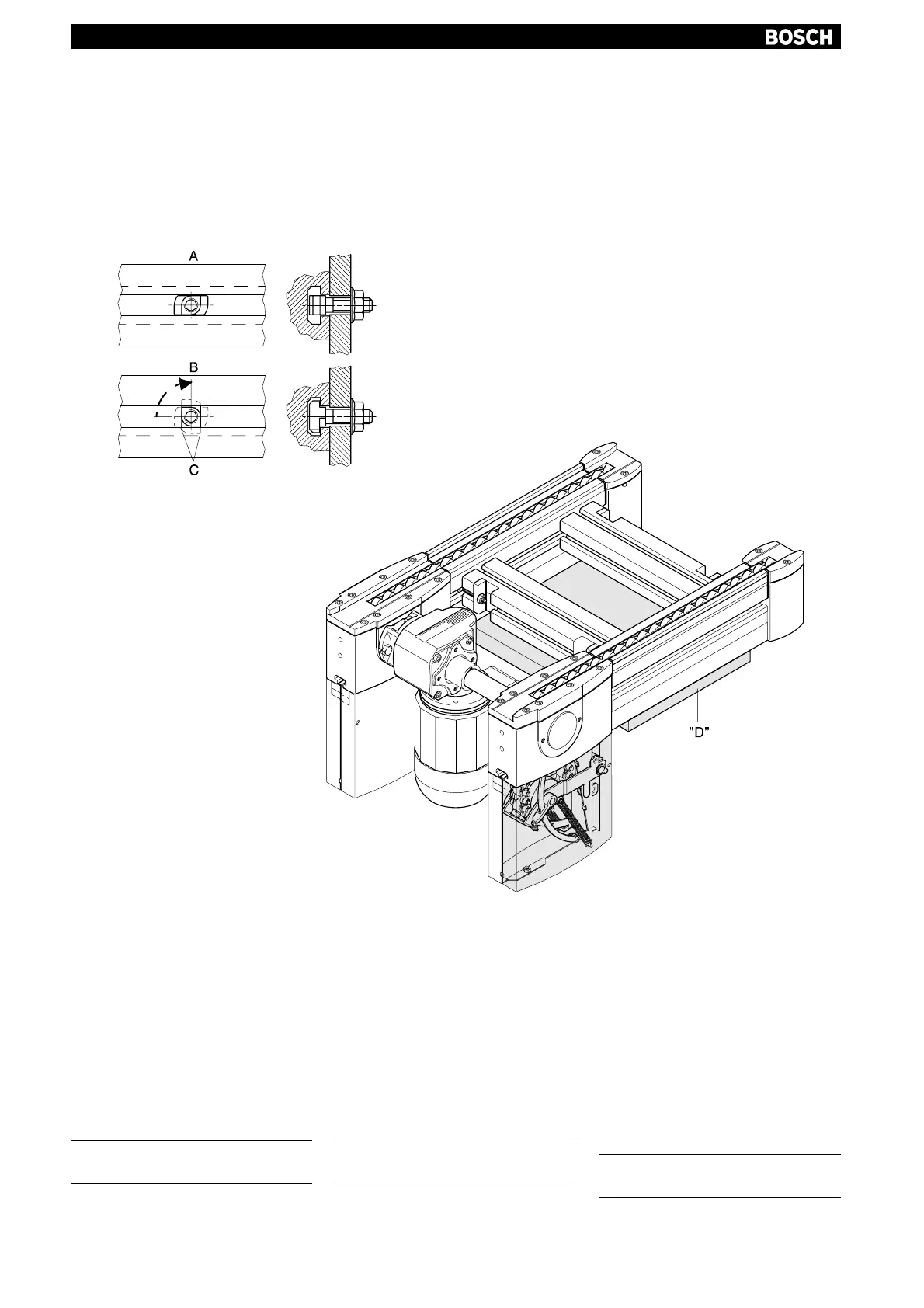
Allgemeines:
Das Befestigen der Baueinheit BS 2/R
im Transfersystem erfolgt nach dem
Hammerschraubenprinzip.
Max. Anzugsdrehmoment 25 Nm.
A = Einsatzlage
B = Klemmlage
C = Anlage in Nut
(Drehmomentstütze)
Transportsicherung "D" erst nach dem
Einbau entfernen (Fig. 6)!
yy
General:
The BS 2/R unit is secured in the
transfer system using the T-bolt
principle.
Max. torque 25 Nm.
A = Position on insertion
B = Clamping position
C = Arrangement in groove
(torque support)
Only remove transport retainer "D" after
installation! (Fig. 6)
yyy
Généralités :
La fixation du composant BS 2/R sur le
système de transfert est assurée suivant
le principe de la vis à tête rectangulaire
(Fig. 4).
Couple de serrage max. 25 Nm.
A = Position d'insertion
B = Position de serrage
C = Position dans la rainure
(support du couple)
Ne retirer la sureté de transport « D »
qu’après le montage ! (Fig. 6)
Einbau in das Transfersystem
Installing in the transfer system
Montage dans le système de transfert
Fig. 6
 Loading...