The CDR 900 will be powered by the vehicle’s 12-volt
battery. If power is not available through the vehicle's
DLC/OBD connector, the user can use the CDR Tool
cigarette lighter adapter connected to the CDR 900
Power and Interface cable to power up the CDR 900.
4.19 Connecting the CDR 900 to an ECU
The CDR 900 kit includes an interface cable (CDR 900
Power and Interface Cable) which connects directly to
vehicle specific CDR cables for downloading data while
directly connecting to an ECU. An adapter is also pro-
vided which allows the CDR 900 to connect with older
CDR cables which were released prior to the CDR 900.
Refer to the CDR Tool Software help file for determing
which CDR cable to use for supported vehicles.
4.19.1 Powering the CDR 900 for Direct ECU connec-
tions
The CDR 900 is powered using the CDR power supply
connected directly to the CDR 900 Power and Interface
Cable. Also, the CDR Tool cigarette lighter adapter can
also be used to power the CDR 900 utilizng a 12V pow-
er source from the vehicle.
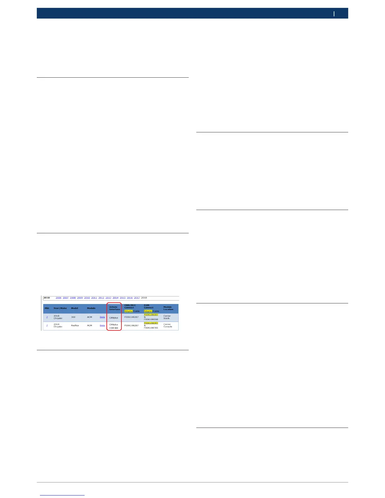
4.20 Supported Vehicles
The CDR Tool Software (version 17.8 and later) help file
contains a Vehicle and Cable Lookup section which lists
all of the supported vehicles by the CDR Tool and the
CDR 900. Always refer Vehicle and Cable Lookup section
for vehicles which are supported by the CDR 900.
4.21 Finishing Up
After using the CDR 900, a few simple steps help you
leave the vehicle electronic system(s) in the proper
state and ensure that you get the most use out of your
diagnostic tools:
1. Before turning the CDR 900 off, exit any running PC
computer applications.
2. Turn the CDR 900 off by removing power. The Power
LED turns off.
3. Disconnect the CDR 900's DLC cable from the ve-
hicle.
4. Disconnect the USB cable from the PC and the CDR
900.
5. Store the CDR 900, cables, and other parts in a
secure, dry location.
5. Troubleshooting
This section is intended to help you get back on track
if the CDR 900 appears to be operating abnormally. In
addition, the most likely cause for the condition is given
as well as other possible causes and recommendations
on how to isolate or eliminate the problem.
5.1 CDR 900 Does Not Pass Power On
Self-Test (POST)
Most Likely Cause:
• Internal problem in the CDR 900.
Recommendations:
• Connect the CDR 900 to a PC using USB and per-
form the recovery procedure.
5.2 CDR 900 Error LED Lights After
Power On
Most Likely Cause:
• A problem has been detected during power on.
Recommendations:
• Power down the VCI and verify that it has the same
problem when you power up again.
• Connect the VCI to a PC using USB and perform
the recovery procedure.
5.3 CDR 900 Fails to Power Up
The CDR 900 should power up as soon as external
power is applied through the CDR Power and Interface
Cable. If the CDR 900 does not turn on, first check the
cable connections. Try supplying power to the device
from two different power sources— the vehicle DLC con-
nector and the USB connector.
Recommendations:
• Check that the cables are securely attached to the
VCI and the connector pins are clean.
• If connecting to the vehicle DLC connector, try
powering from the USB connector.
• If powering from USB, try powering from the ve-
hicle DLC connector.
5.4 Vehicle LED is Blinking Red
If the CDR 900 does not detect 12V on Pin 16 of the
DLC cable or that power is appled to CDR 900 Power
and Interface Cable, the CDR 900 will inform the user by
automatically turning on and blinking the Vehicle LED