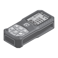
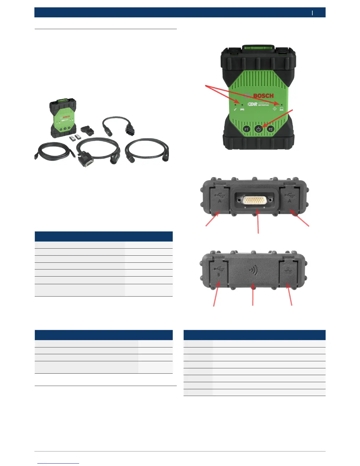
Item Description
1 LED Indicators
2 Power Button with LED indicator
3 USB Port Type A (currently not used for CDR 900)
4 DB26 Connector (CDR Power and Interface cable)
5 USB Port Type A (currently not used for CDR 900)
6 USB Port Type B - PC Connection Port
7 Wireless Adapter
8 Ethernet Port (currently not used for CDR 900)
___
3
4
5
6 7 8
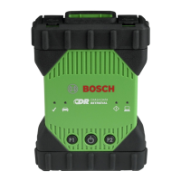
4.4 CDR 900 Components
The CDR 900 components include cables and hardware
needed to connect to and download EDR data from ve-
hicles through the OBD connector or directly from the
vehicle's ECU. Depending on the kit purchased, all of
the cables and components shown below are included
except for the Wireless Dongle. Wireless dongle avail-
ability depends upon the country the CDR 900 is sold.
The CDR 900 and its components may be offered in a
few possible kit configurations such as a CDR 900 Up-
grade Kit (P/N 1699200630) or kits which may combine
the CDR 900 and the CDR DLC Basic Kit with the older
style CDR vehicle interface (CANplus Module). Regard-
less of the kit offered, the CDR 900 main components
consist of the following:
CDR 900 Components Part Number Qty
CDR 900 VCI Assembly 1699200598 1
CDR 900 Power and Interface Cable 1699200602 1
CDR 900 DLC/J1962 Cable 1699200615 1
CDR 900 Legacy Cable Adapter (D2ML) 1699200616
CDR 900 1 m Extension Cable 1699200617 1
USB A to B, Heavy Duty 3m Cable 1699200385 1
Wireless 802.11n Dongle (optional de-
pending on where kit is sold)
1699200155 2
Optional accessories for the CDR 900 are listed in the
following table.
Item Part Number
Bosch Storage Case (Nylon Case) F00K108939
CDR 12V Power Supply, with Power Cord F00E900104
CDR 12V Power Supply, without Power Cord 02002435
Wireless 802.11n Dongle (available only in
certain countries)
1699200155
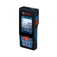
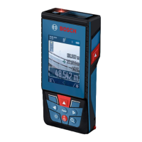
4.5 CDR 900 Assembly Connectors,
Lights and Controls
A number of standard connectors, controls and LEDs
are available on the CDR 900 to facilitate operation and
communication with vehicles, PCs and local area net-
works. These connectors and controls are shown in the
following illustrations.
1
2