• Although the VCI and accessories are water resis-
tant, they are not waterproof; thoroughly dry them
prior to storage.
• Avoid using harsh solvents such as petroleum
based cleaning agents, Acetone, Benzene, Trichlo-
roethylene, etc.
6.2 Recovering the CDR 900 Software
As a result of a power failure or a communications error
during a software update, the CDR 900 software may
become corrupted. You may see several symptoms such
as error messages directing you to go to RECOVERY
mode or an inability to connect to a detected CDR 900.
The following two error messages generally occur dur-
ing CDR 900 Tester Software download. If you see
either of these messages, perform the Recovery Proce-
dure.
• "Error reprogramming the VCI. Go to Recovery
Mode."
• "There was a problem reprogramming the VCI"
6.2.1 Recovery Procedure
Use the following procedure to recovery the software
on the CDR 900.
1. Press and hold the Power button of the CDR 900
down. Release the button when the red Error LED
is illuminated. After Error LED is illuminated, the
CDR 900 is ready for recovery and the Error LED
will remain on.
2. Start the CDR 900 VCI Manager software by click-
ing the CDR 900 VCI Manager icon on your desktop.
Your CDR 900 must be connected via USB or it will
not be recognized.
3. When the CDR 900 is detected by the CDR 900 VCI
Manager software, the icon will be labeled with
"Recover".
4. Select the CDR 900 without the serial number and
click the Recover button. The CDR 900 VCI Manager
software switches automatically to the CDR 900
Update tab.
• The Recovery Procedure removes any embed-
ded application software loaded on the CDR
900. Your network settings will be retained.
5. Select the latest version of the CDR 900 Recovery
Image and click Start Update. Do not unplug the
CDR 900 from the PC or remove power from the
CDR 900 during the recovery process.
6. When you see the message indicating that the CDR
900 will automatically restart, click OK. The CDR
900 VCI Manager software switches automatically
to the VCI Explorer tab, and your CDR 900 appears
when it has finished the restart and Power On Self
Test (POST).
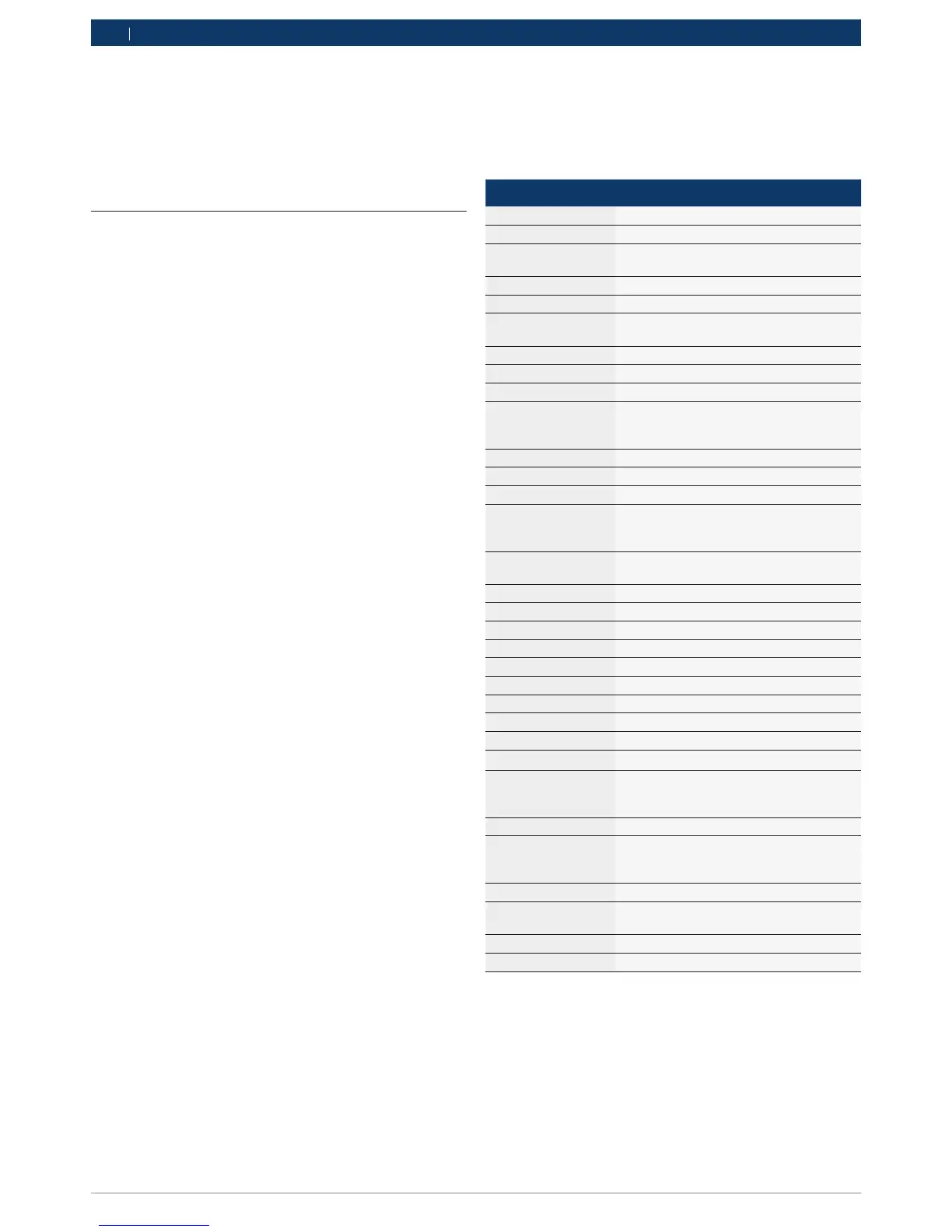
7. Glossary
Here is a glossary of terms commonly used in the Auto-
motive Diagnostics industry. For CDR Tool terms, refer
to the CDR Tool Software Help File.
TERM DESCRIPTION
TERM DESCRIPTION
AC ALTERNATING CURRENT
BAUD RATE THE SPEED AT WHICH DATA IS TRANS-
FERRED OVER A SERIAL DATA LINK
BPS BITS PER SECOND
CDR CRASH DATA RETRIEVAL
CURSER HIGHLIGHTED TEXT OR DATA ON A DIS-
PLAY SCREEN
DC DIRECT CURRENT
DCE DATA COMMUNICATION EQUIPMENT
DLC DATA LINK CONNECTOR
DTE DATA TERMINAL EQUIPMENT. A TERM
USED TO DESCRIBE A DEVICE CON-
NECTED TO AN RS232 LINK.
ECM ENGINE CONTROL MODULE
ECU ENGINE CONTROL UNIT
EEPROM ELECTRONICALLY ERASABLE PROM
ETHERNET STANDARDIZED IEEE 802.3 TWISTED-
PAIR WIRE FOR CONNECTING SYSTEMS
TO A NETWORK.
HZ HERTZ - A UNIT OF MEASURE FOR FRE-
QUENCY
I/F INTERFACE
I/O INPUT/OUTPUT
I/P INSTRUMENTATION PORT
LAN LOCAL AREA NETWORK
LED LIGHT-EMITTING DIODE
OBD ON BOARD DIAGNOSTICS
OEM ORIGINAL EQUIPMENT MANUFACTURER
PC PERSONAL COMPUTER
RCV RECEIVE
RS232 SAME AS RS232C
RS232C THE MOST STANDARD SERIAL COM-
MUNICATION INTERFACE USED IN THE
COMPUTER INDUSTRY
SCI SERIAL COMMUNICATION INTERFACE
USB UNIVERSAL SERIAL BUS - A COMMON
STANDARD FOR INTERFACING WITH A
PC
VCI VEHICLE COMMUNICATION INTERFACE
CDR 900 VCI MAN-
AGER
PC SOFTWARE THAT CONFIGURES,
TESTS, AND UPDATES THE CDR 900
VDC VOLTS DC
WLAN WIRELESS LOCAL AREA NETWORK