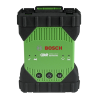
icon red. This condition might be seen if the CDR 900
is only powered by a 5V USB connection from your PC
or if the OBD Cable has accidently been disconnected
from the vehicle Data Link Connector (DLC/OBD) and
is powered from the backup capacitor inside the device
When the CDR 900 detects 12V on Pin 16 or when pow-
ered though the cable, the Vehicle LED will stop blink-
ing red.
Recommendations:
• Ensure 12V is applied to the CDR 900 Power and
Interface Cable or Pin 16 of the DLC/OBD cable
5.5 CDR 900 Speaker is Beeping
If the CDR 900 is performing diagnostic services for the
PC and does not detect 12V on Pin 16 of the DLC cable,
the CDR 900 will inform the user of the loss of power
by beeping the speaker. The CDR 900 will continue to
beep until the backup capacitor is drained. When the
CDR 900 detects 12V on Pin 16, the speaker will stop
beeping.
Recommendations:
• Ensure 12V is applied to Pin 16 of the DLC cable
during a download or that 12V power is supplued
to the CDR 900 through the CDR 900 Power and
Interface Cable.
5.6 CDR 900 Turns Off Immediately
When Disconnected from the Vehicle
During or After an EDR Download
If the CDR 900 does not remain on during a DLC dis-
connection, there may be a problem charging the inter-
nal capacitor.
The CDR 900 should remain powered up if power is
lost during engine cranking or after it is disconnected
from power (vehicle DLC) during a diagnostic session.
The CDR 900 speaker will beep to notify the user that
power has been lost unexpectedly during the diagnostic
session.
Recommendations:
• Check for 12V power supply at the vehicle DLC con-
nector
• Ensure that the CDR 900 has been connected to
the vehicle DLC for at least 90 seconds to charge
the internal capacitor.
5.7 CDR 900 Checkmark LED is Blinking
If the internal temperature of the CDR 900 has exceed-
ed the maximum limit, the CDR 900 will automatically
turn off the wireless adapter. This will be visible to the
user by the Checkmark LED blinking. When the internal
temperature of the CDR 900 lowers to an acceptable
value, the wireless adapter will be re-enabled for wire-
less communication.
Recommendations:
• Move the CDR 900 to a cooler location near the
vehicle
5.8 Wireless Communication with Net-
work Unsuccessful using the Wire-
less 802.11n Dongle
The wireless dongle communication to a network. The
wireless dongle is only intended to be used with the
CDR 900 for Point-to-Point communication or Infra-
structure wireless communication.
Recommendations:
• Make sure you do not have two D-Link wireless
dongles connected to the PC.
• Make sure you are not trying to connect the PC
to your dealership network using the DWA131 E1
dongle.
5.9 CDR 900 VCI Manager Displays the
Yellow Icon over the VCI after previ-
ous use
There may be instances when Windows does not rec-
ognize the installation of the wireless dongle. In these
cases, Windows may create a new wireless profile in-
stead of using the existing one already stored on the
PC. The yellow icon displayed over your CDR 900 in-
structs you to plug in the USB cable between the CDR
900 and the PC.
Recommendations:
• Always use Windows to safely Eject the wireless
adapter before physically removing it from your PC.
• Unplug and then re-install your wireless adapter.
Windows will attempt to recognize the wireless
adapter. If successful, the yellow icon will disap-
pear and the CDR 900 will be ready for wireless
Point-to-Point communication.
5.10 PC Application is Unable to Commu-
nicate with the CDR 900 over USB
CDR 900 VCI Manager Software must be installed on
the PC, and the CDR 900 must be powered up before
it will communicate. The CDR 900 must be configured
through USB before it will communicate using any other
connection types.
Recommendations:
If other applications including the CDR 900 VCI Man-
ager are able to connect to the CDR 900 then: