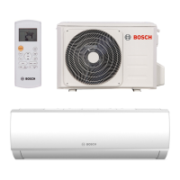
6 CLIMATE 5000 RAC SINGLE SPLIT (R32) – 6720894076 (2019/08)
Specifications
2 Specifications
2.1 Model Reference
Refer to the following table to determine the specific indoor and outdoor unit model number of your purchased equipment.
Indoor Unit Model Outdoor Unit Model Capacity (kW)
Power Supply
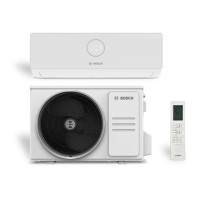
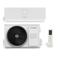
Climate 5000 RAC 2,6-2 / 2,6-3 IBW Climate RAC 2,6-2 OUE
2,6
220-240V~, 50Hz,
1Phase
Climate 5000 RAC 3,5-2 / 3,5-3 IBW
Climate RAC 3,5-2 OUE
3,5
Climate 5000 RAC 5,3-2 / 5,3-3 IBW Climate RAC 5,3-2 OUE
5,3
Climate 5000 RAC 7-2 / 7-3 IBW Climate RAC 7-2 OUE
7
Table 1.
2.2 Electrical Wiring Diagrams
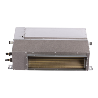
2.2.1 Indoor unit
Abbreviation
Paraphrase
Y/G Yellow-Green Conductor
ION
Positive and Negative Ion Generator
CAP
Capacitor
PLASMA
Electronic Dust Collector
L
LIVE
N
NEUTRAL
Heater
The Electric Heating Belt of Indoor Unit
T1
Indoor Room Temperature
T2
Coil Temperature of Indoor Heat Exchanger Middle
Table 2.
Indoor Units 2,6-2 / 3,5-2 / 5,3-2 / 7-2 / 2,6-3 / 3,5-3 / 5,3-3 / 7-3 IBW
P1
P2
S
X Y E 12V/5V
HA HB
4
3
M M
M
5(3or2)
ION
3
2
CN701
2
INDOOR WIRING DIAGRAM
MAIN BOARD
OPTIONAL
CAP
OPTIONAL
HEATER
WHITE
INDOOR UNIT
OUTDOOR UNIT
RED
BLUE (BLACK)
YELLOW
Y/G
OPTIONAL
OPTIONAL
OPTIONAL
OPTIONAL
OPTIONAL
OPTIONAL
DISPLAY BOARD
MULTI-FUNCTION CONTROL BOARD
ROOM TEMPERATURE
SENSOR
FOR SETTING NETADDRESS (CCM Comm.Bus)
ENC3+F1
(MULTI-FUNCTION
CONTROL BOARD)
CODE
ON ON ON ON
NETADDRESS
FACTORY SETTING
To Remote SwitchTo Remote AlarmTo Randomly
Connected
Wire-controller
To CCM Comm.Bus or
485 Wire-controller
Applicable for MULTI and
MONO unit without 1W
standby control feature
-----This symbol indicates the
element is optional,the actual
shape shall prevail.
Applicalbe for MONO unit with
1W standby control feature
Wi-Fi
Controller
Wire Controller
PIPE TEMPERATURE SENSOR
ROOM TEMPERATURE SENSOR
OPTIONAL
OPTIONAL
INDOOR FAN
PLASMA
SWITCH BOARD
SWING MOTOR1
SWING MOTOR2
Applicable to
AC motor only
Y/G
Fig. 1.

 Loading...