Product Information
Climate Class 6000i/8000i – 6721831489 (2022/11)
42
2Product Information
2.1 Declaration of conformity
The design and operating characteristics of this product comply with the
European and national requirements.
The CE marking declares that the product complies with all the
applicable EU legislation, which is stipulated by attaching this
marking.
The complete text of the Declaration of Conformity is available on the
Internet: worcester-bosch.co.uk.
2.2 Simplified EU Declaration of Conformity regarding
radio equipment
Bosch Thermotechnik GmbH hereby declares, that the Climate Class
6000i/8000i product described in these instructions complies with the
Directive 2014/53/EU.
The complete text of the EU Declaration of Conformity is available on the
Internet: worcester-bosch.co.uk.
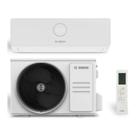
2.3 Scope of delivery
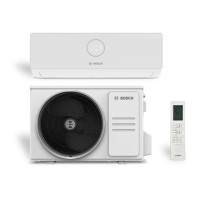
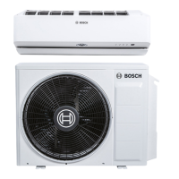
Key to Fig. 1:
[1] Outdoor unit (filled with refrigerant)
[2] Indoor unit (filled with nitrogen)
[3] Mounting Plate
[4] Mirror sheet metal (only for coloured product types
CLC8001i... T/S/R)
1)
[5] Terminal cover with screw
[6] Remote control with batteries
[7] Set of printed documents for product documentation
[8] Fixing materials (7 long screws, 1 special screw for fixing the
remote control and 8 wall plugs)
[9] Sheet metal (for fixing the cable in the strain relief)
[10] Drainage connection and drainage tray
(only for product types CLC8001i...)
[11] Drainage connection (only for product types CLC6001i...)
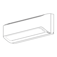
2.4 Product dimensions and minimum clearances
2.4.1 Indoor unit and outdoor unit
Fig. 2
[1] Wall plug (scope of delivery)
[2] Special screw (scope of delivery)
A CLC8001i... model
B CLC6001i... model
2.4.2 Refrigerant lines
Key to Fig. 3:
[1] Pipe on gas side
[2] Pipe on liquid side
[3] Siphon-shaped elbow as oil separator
If the outdoor unit is positioned higher than the indoor unit, install a
siphon-shaped elbow on the gas side after no more than 6m and every
6 m thereafter ( Fig. 3, [1]).
▶ Observe maximum pipe length and maximum difference in height
between indoor unit and outdoor unit.
Table 2 Pipe length and difference in height
Table 3 Pipe diameter depending on unit type
Table 4 Alternative pipe diameter
Table 5
3 Installation
3.1 Before installation
CAUTION
Risk of injury from sharp edges!
▶ Wear protective gloves during installation.
CAUTION
Danger of burns!
During operation the pipes become hot.
▶ Make sure, that the pipes cooled down before touching them.
▶ Check the scope of delivery for damage.
▶ Check whether a hissing sound due to negative pressure can be
detected when opening the pipes of the indoor unit.
3.2 Requirements for installation location
▶ Observe minimum clearances ( Fig. 4 ).
IDU
▶ Do not install the indoor unit in a room in which open ignition sources
(for example: open flames, an operating wall mounted gas boiler or
an operating electric heating system) are in operation.
▶ The appliance can be installed in a room with a floor area of 4 m
2
,
if the installation height is at least 2.5 m. If the installation height is
lower, the floor area must be accordingly larger.
▶ The installation location must not be higher than 2000 m above
sea level.
1) Fastening the mirror metal sheets Fig. 10
Maximum pipe
length
1)
[m]
1) Gas side or liquid side
Maximum height
difference
2)
[m]
2) Measured from bottom edge to bottom edge.
All types ≤ 15 ≤ 10
Pipe size
Unit type Liquid side [mm] Gas side [mm]
All types 6.35 (1/4") 9.53 (3/8")
Pipe diameter [mm] Alternative pipe diameter [mm]
6.35 (1/4") 6
9.53 (3/8") 10
Specification of the pipes
Min. piping length 3 m
Additional refrigerant if the pipe length
exceeds 7.5 m (liquid side)
CLC6001i...: 15 g/m
CLC8001i...: 0 g/m
1)
1) Prefilled for maximum pipe length of 15 m.
Pipe thickness with 6.35 mm to 12.7 mm
pipe diameter
≥0.8mm
Thickness of insulation against heat ≥ 6 mm
Material of insulation against heat Polyethylene foam
OBJ_DCL-6721831489-005.fm Page 42 Wednesday, October 13, 2021 11:10 AM
 Loading...