|
Installation Guide | Contents
.
Bosch Security Systems B.V. | 2020.03 | F01U011791-03 3
Contents
1.0 Introduction ......................................... 4
2.0 Overview .............................................. 4
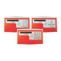
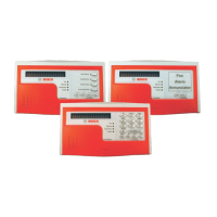
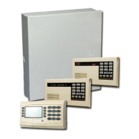
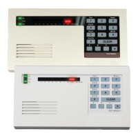
2.1 D1255RB/D1256RB/D1257RB Features 4
2.1.1 D1255RB ............................................... 4
2.1.2 D1256RB ............................................... 4
2.1.3 D1257RB ............................................... 4
2.2 Description ............................................ 4
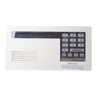
2.2.1 Display .................................................. 4
2.2.2 Audible Tones ........................................ 5
2.2.3 Switch Settings ..................................... 5
3.0 Installation ........................................... 6
3.1 Mounting Information (D1255RB,
D1256RB, and D1257RB) ...................... 6
3.2 Wiring Information (D1255RB, D1256RB,
and D1257RB) ....................................... 6
3.3 Installation Procedure ........................... 6
4.0 D1256RB Programming Requirements .....
............................................................ 9
4.1 Keypad (COMMAND CENTER)
Assignments .......................................... 9
4.2 Area Text ............................................. 10
4.2.1 D9412GV4/D7412GV4/D7212GV4 v1.xx
and earlier versions ............................. 10
4.2.2 B9512G/B8512G and
D9412GV4/D7412GV4/D7212GV4 v2.xx ..
............................................................ 11
4.3 Custom Functions ............................... 11
4.4 Function List ....................................... 12
4.4.1 Menu Item and Function ...................... 13
4.4.3 Passcode Worksheet ........................... 14
4.4.4 Passcode ............................................. 14
4.4.5 Keypad (Command Center) Functions . 15
5.0 Specifications ..................................... 17
Figures
Figure 1: D1255RB, D1256RB, and D1257RB
Internal Arrangement ....................... 5
Figure 2: Releasing the Enclosure Base .......... 6
Figure 3: Lifting the Keypad from the
Enclosure Base ................................ 6
Figure 4: Removing the Enclosure Base .......... 7
Figure 5: Lifting the Red Cover ....................... 7
Figure 6: Removing the Red Cover ................. 7
Figure 7: Removing the Faceplate .................. 7
Figure 8: Setting the Address Switches .......... 8
Figure 9: Address DIP Switches ..................... 8
Figure 10: Mounting the Enclosure Base .......... 8
Figure 11: Wiring Harness Connection to Keypad
or Annunciator ................................. 9
Figure 12: Installing the Enclosure Base − Top . 9
Figure 13: Closing the Enclosure Base – Bottom
........................................................ 9
Figure 14: Example – Area Text for Fire
Applications ................................... 10
Figure 15: Example – Area Arming Text for Fire
Applications ................................... 11
Figure 16: Example – Custom Functions
Recommended for UL864 9
th
Edition
...................................................... 11
Figure 17: Example – Function List ................ 12
Figure 18: Example – Fire Passcode Worksheet
...................................................... 14
Figure 19: Example – Keypad Functions ......... 15
Figure 20: Custom Functions ......................... 16
Tables
Table 1: DIP Switch Address Settings ........... 8
Table 2: Keypad or Annunciator Connections 8
Table 3: Function List Description .............. 13
Table 4: Specifications for the D1255RB and
D1256RB Keypads and the D1257RB
Annunciator ................................... 17