Do you have a question about the Bosch D7212G and is the answer not in the manual?
Explains the structure of the guide and lists related documentation.
Lists the technical specifications for the D7212G control/communicator.
Details the key features and functionalities of the D7212G control/communicator.
Provides general installation procedures and references to other sections.
Details how to connect the system to earth ground for safety.
Details the primary AC power circuit and transformer connections.
Explains the secondary DC power source, including battery requirements.
Details the combined power output for all powered devices.
Covers programming for relay outputs at terminals 6, 7, and 8.
Instructions for connecting the telephone cord to the panel and jack.
Describes how the system handles communication failures.
Details wiring on-board points and using end-of-line resistors.
Explains how debounce count affects point response time.
Describes POPIT modules used for off-board point expansion.
Details the OctoPOPIT module for eight off-board points in one unit.
Covers the D8129 OctoRelay for adding relay outputs to the system.
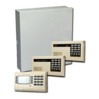
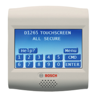
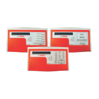
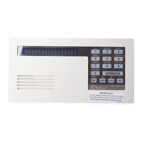
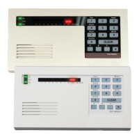
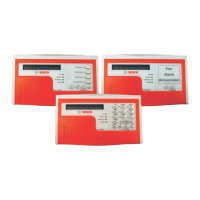
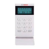
Details the 4-wire powered command centers used for arming and status annunciation.
Describes connecting keyswitches for arming/disarming areas.
Covers connecting a parallel printer to the panel.
Details the serial interface module for RS232 devices.
Procedure for connecting and disconnecting the D5200 programmer.
Illustrates the D7212G panel faceplate and its components.
Shows the first part of the D7212G system wiring diagram.
Provides a chart for assigning addresses to ZONEX 1 points.
| Backlit | Yes |
|---|---|
| Type | Keypad |
| Display | LCD |
| Keypad Layout | Standard |
| Sounder | Yes |
| Tamper Protection | Yes |
| Voltage | 12 VDC |
| Dimensions | 4.5 in x 6.3 in x 1.0 in (11.4 cm x 16.0 cm x 2.5 cm) |
| Operating Temperature | 32°F to 120°F |