Home
Bosch
Keypad
D7212G
Page 63 (D7212 G Control;Communicator, 3 of 3)
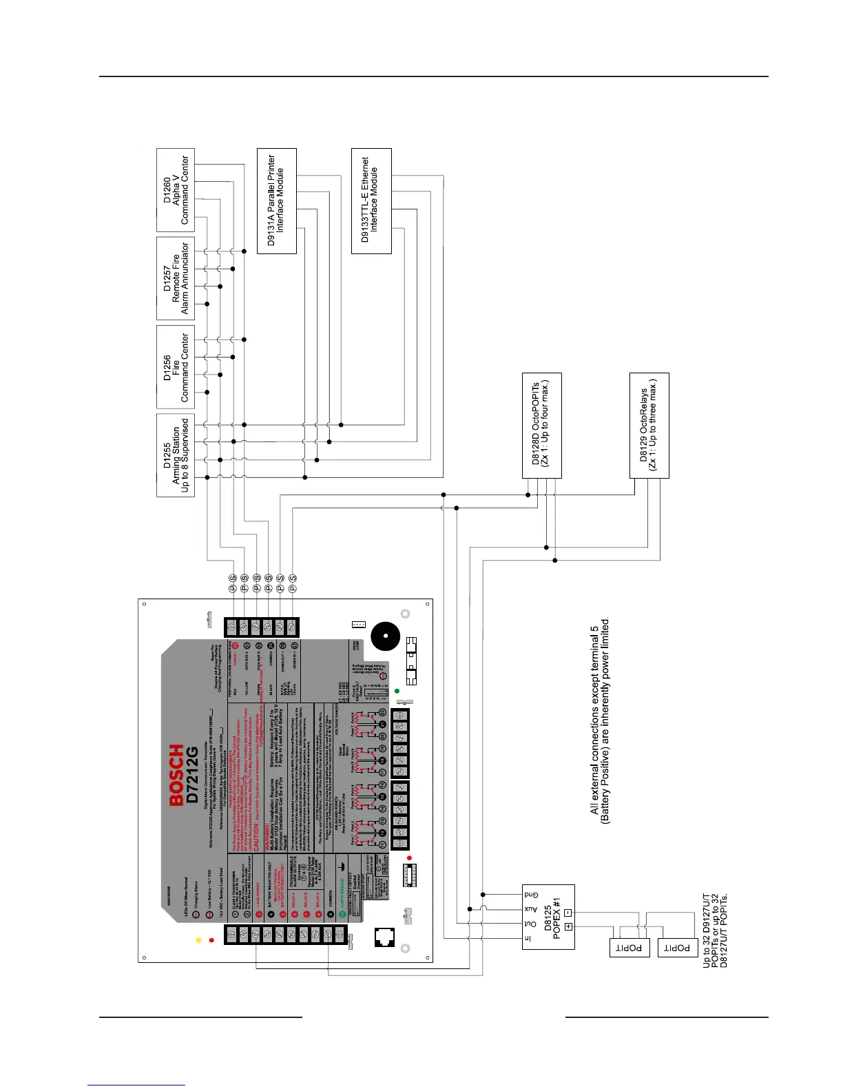
Bosch D7212G - D7212 G Control;Communicator, 3 of 3; Figure 22 C: D7212 G System Wiring Diagram, 3 of 3
68 pages
Manual
Save Page as PDF
To Next Page
To Next Page
To Previous Page
To Previous Page
Loading...
D7212G Operation and Installation Guide
D7
2
1
2G
Page 63
© 2003 Bosch Security Systems
499
8
1
3
8544C
Appendix A: System Wiring Diagrams, Issue A
A.
3
D7212G Control/Communicator, 3 of 3
Figure 22c: D7212G System Wiring Diagram, 3 of 3
62
64
Table of Contents
Main Page
Default Chapter
3
Table of Contents
3
1 Introduction
9
Guide Organization
9
Table 1: D7212G Operation and Installation Guide Organization
9
Related Documentation
10
Documentation Conventions
10
Type Styles Used in the Text
10
Table 2: Related Documentation
10
Tips, Notes, Cautions and Warnings
11
FCC Rules
11
Part 15
11
Part 68
11
2 Overview
13
9000G Series Panel Differences
13
Figure 1: System Configuration
13
Table 3: Differences between the 9000G Series Panels
13
Specifications
14
Table 4: Specifications
14
Compatible Accessories
16
Features in D7212G
16
Introduction
16
Ground Fault Detect
16
Added Feature When Using Ground Fault Detect
17
Netcom Functionality
17
Standard Features
17
Points
17
Areas and Accounts
17
Communicator
17
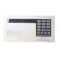
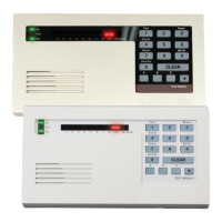
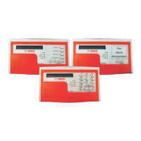
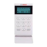
Command Centers
18
Keyswitch
18
Event Memory
18
Event Log
18
EMI & Lightning Transient Protection
18
Programming
18
Table 5: Compatible Command Centers
18
Other Features
19
Control/Communicator Assembly
19
Components and Literature Available by Separate Order
19
Listings and Approvals
20
Table 6: Listings
20
3 Installation
21
Before Beginning
21
Enclosure Options
21
Beginning the Installation
21
Figure 2: Enclosure Mounting
21
Installing the Assembly
22
Connecting Earth Ground
22
Terminal
22
Ground Fault Detect Enable
22
Locking the Reset Pin
22
Figure 3: Ground Fault Detect
22
Figure 4: Reset Pin
22
Finishing the Installation
23
Charge the Battery While Finishing
23
Install and Wire Detection Devices
23
Install Modules and Relays
23
Make the Telephone Connections
24
Connect the On-Board Points and Command Centers
24
Power up
24
Programming the Panel
24
Install the Point Chart Label
24
Testing the System
24
4 Power Supply
25
Primary Power Terminals
25
Primary (AC) Power Circuit
25
Installing the Transformer
25
Secondary Power Terminals
25
Secondary (DC) Power
25
Installing the Battery
26
Replacing the Battery
26
Figure 5: Non Power Limited Wiring
26
Battery Supervision
27
Battery Charging Circuit
27
Battery Discharge/Recharge Schedule
27
Table 7: Battery Discharge/Recharge Schedule
27
Charging Status and Low Battery Leds
28
Figure 6: Charging and Battery Leds
28
Table 8: Charging Status and Low Battery Leds
28
5 Power Outputs
29
Circuit Protection
29
Total Available Power
29
Aux Power Terminals
29
5.3.1 Continuous Current Draw
29
Programmable Power Outputs Terminals
29
Programming
29
Optional Relays Required
30
Terminals 6 and 7
30
Fire System Power Formula
30
Terminal 8
30
Figure 7: Relays for Terminals 7 and 8 and Ground Start
30
6 Telephone Connections
31
Registration
31
Notification
31
Location
31
Phone Cord Connection
31
Phone LED (Red)
31
Figure 8: RJ31X Wiring
31
Figure 9: Phone Connector and LED and Operation Monitor LED Locations
31
Operation Monitor LED (Green)
32
Dialing Format
32
Phone Line Monitor
32
Called Party Disconnect
32
Communication Failure
32
Enhanced Communication
32
Ground Start
33
Relay Installation
33
Phone Monitor Select Jumper
33
Figure 10: Phone Monitor Select
33
7 On-Board Points
35
Description Terminals
35
Point Sensor Loops
35
Point Parameters
35
Point Response Time
35
Figure 11: On-Board Point Sensor Loop Wiring
35
Wiring Information for Installations Using the Ademco AB-12 Bell/Housing
36
Figure 12: Wiring for Installations Using the Ademco AB-12 Bell/Housing
36
8 Off-Board Points
37
Point (ZONEX) Bus D7212G Terminals
37
D8125, D8127 and D9127 POPIT Modules
38
Listings
38
Installing the D8125 POPEX Module
38
Mounting
38
Wiring the D8125 to the Control/Communicator
38
Wiring Popits to the Data Expansion Loop
38
Wiring Data Expansion Loops to POPEX Modules
39
POPIT Sensor Loops
39
Table 9: Data Expansion Loop Wire Specifications
39
Figure 13: Connecting the D8125 POPEX to the D7212G Panel
40
POPIT Module Point Assignments
41
Program Record Sheet
41
Figure 14: Program Record Sheet
41
D8128D Octopopit Module
42
Description
42
Listing
42
Installing the Octopopit
42
Wiring Octopopits
43
Line Termination
43
Octopopit Sensor Loops
44
Address Assignment Switches
44
Testing Off-Board Points
44
Table 10: D8128D Octopopit Switch Settings for D7212G
44
Figure 15: Connecting D8128D Octopopits to the D7212G
45
9 Off-Board Relays
47
D8129 Octorelay
47
Configuring the D8129 Octorelay
47
Relay Outputs
47
Installation
47
Wiring Connections
47
Table 11: D8129 Octorelay Switch Settings
47
Figure 16: D8129 Connections to the D7212G
48
10 Arming Devices
49
Description
49
Command Center Terminals
49
Assigning the Command Center an Address
49
Table 12: Command Cneter Address Settings
49
Installation
50
Figure 17: Power at Command Centers
50
Table 13: Command Center Connections
50
D279A Independent Zone Control
51
Keyswitch
51
Description
51
Programming
51
Installation
51
Keyswitch Operation
51
Figure 18: Keyswitch Wiring
51
11 0 SDI Devices
53
Description
53
Installation
53
D9131A Parallel Printer Interface Module
53
Switch Settings
53
Supervision
53
Table 14: SDI Device Connections
53
Table 15: Printer Address Switch Settings
53
SDI Address 80
54
D9133 Serial Interface Module
54
Address Settings
54
Supervision
54
SDI Address 88
54
D9133DC Direct Connect Programming Module
54
11.5. 1 . 1 Connecting the D9133DC
54
11.5. 1 .2 Used as an External Modem
54
D9133TTL-E Network Interface Module
55
Address Settings
55
Supervision
55
12 Programmer and Accessory Connections
57
Programmer Connector
57
Programmer Access Reports
57
Accessory Connector
57
Figure 19: Reset Pin
57
Figure 20: Programmer and Accessory Connections
58
13 Faceplate
59
D7212G Faceplate
59
Figure 21: D7212G Faceplate
59
Appendix A: System Wiring Diagrams, Issue a
61
D7212G Control/Communicator, 1 of 3
61
Figure 22A: D7212G System Wiring Diagram, 1 of 3
61
D7212G Control/Communicator, 2 of 3
62
Figure 22B: D7212G System Wiring Diagram, 2 of 3
62
D7212G Control/Communicator, 3 of 3
63
Figure 22C: D7212G System Wiring Diagram, 3 of 3
63
Appendix B: Point Address Chart
65
ZONEX 1, Points 9 to 40
65
Table 16: ZONEX 1 Point Address Chart
65
Other manuals for Bosch D7212G
Manual
16 pages
Related product manuals
Bosch D720
34 pages
Bosch D1260
154 pages
Bosch D8229
4 pages
Bosch D1265
92 pages
Bosch D1255RB
44 pages
Bosch D1256RB
20 pages
Bosch D1255/D1255B
8 pages
Bosch D220A series
2 pages
Bosch D1260 Series
3 pages
Bosch DS7447V2 Series
3 pages
Bosch D1255RB/D1256RB/D1257RB
20 pages
Bosch 2000
2 pages