10 en | Wiring Powered loop interface
2018.06 | 4.0 | F.01U.036.340 Installation instructions Bosch Security Systems, Inc.
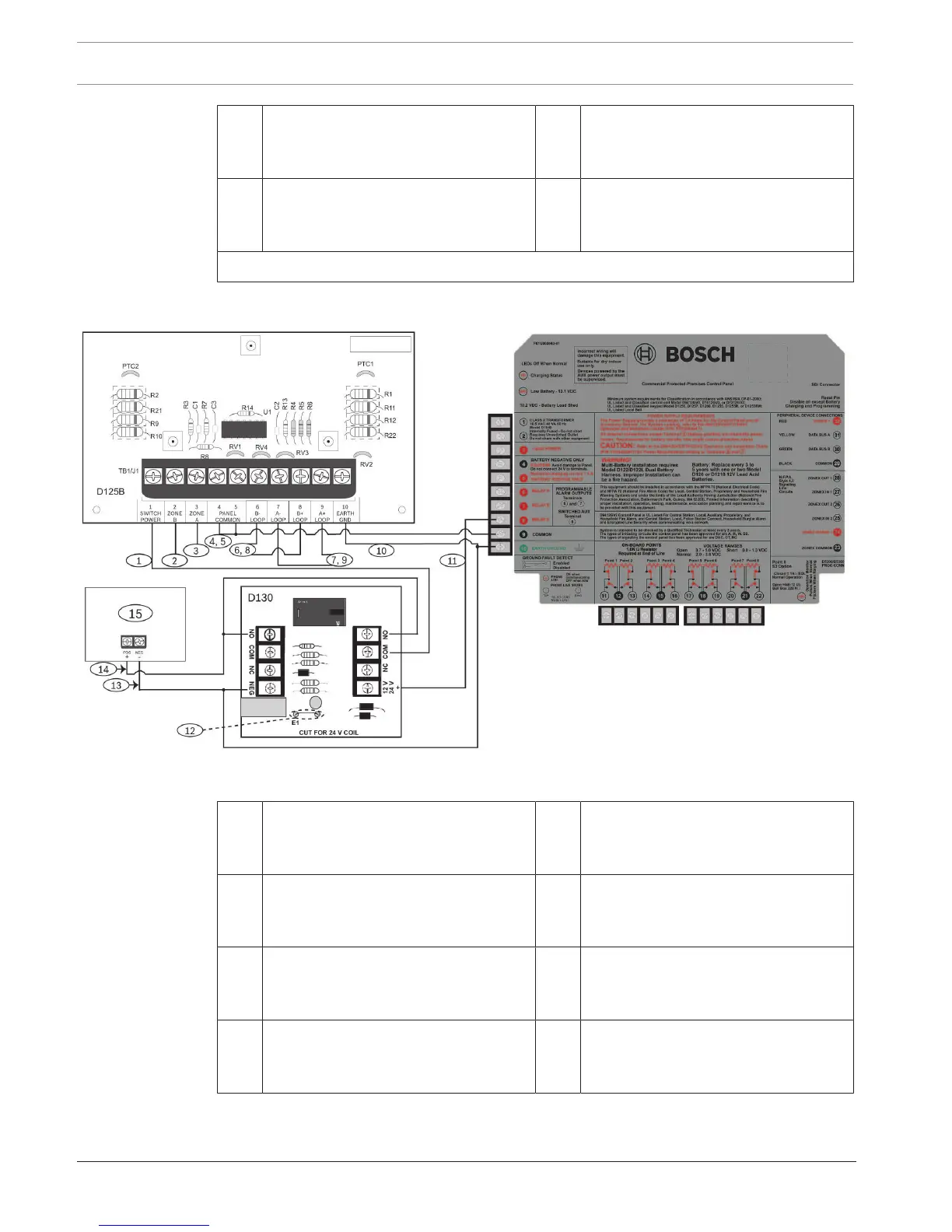
13 Negative connection from the auxiliary
power supply to the negative terminal
of the relay and panel common
14 Positive connection from the auxiliary
power supply to the positive terminals
of the relay
15 UL Listed regulated, power limited
auxiliary power supply (12VDC or
24VDC) for fire protection systems
16 Output A jumper (under cover) set for
auxiliary power applications (AUX
PWR)
1
You can also use output B or C in conjunction with a D133 or D134 relay module
5.3.2 Wiring a G Series panel
Figure5.5: Wiring two-wire loops for power supplied by an external auxiliary power supply controlled by a relay and a G Series
panel
1 Power‑limited, supervised switched
auxiliary power from the switching
relay
2 Supervised connection to Zone B
power from an on‑board point of the
panel
3 Supervised connection to Zone A
power from an on‑board point of the
panel
4 Connection with terminal 5 to only one
common on the panel
5 Connection with terminal 4 to only one
common on the panel
6 Power-limited, supervised negative to
B loop detectors (see Wiring sensor
loops, page 6)
7 Power-limited, supervised negative to
A loop detectors (see Wiring sensor
loops, page 6)
8 Power-limited, supervised positive to B
loop detectors (see Wiring sensor
loops, page 6)